
45
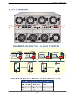
Chapter 6: Data Plane
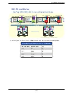
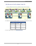
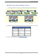
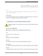
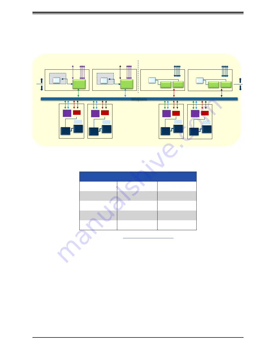
With Ethernet and PassThru Module, Dual CPU
Data Plane of SBI
Switch Module#B1
CPU
Control Plane
SBM-25G-100
500G
802G
-620P in 610J Enclosure with Ethernet Switch and Pass-Thru Module
22
ASIC
Switch Module#B2
ASIC
Node 9
Node 10
Midplane
10x 25G
10x 25G
CPU
Control Plane
SBM-25G-100
Switch Module#A2
Switch Module#A1
PHY
10x 10/25G
5x 100G
SBM-25G-P10
PHY
MCP
PHY
10x 10/25G
5x 100G
SBM-25G-P10
PHY
MCP
1:1
Node 1
Node 2
1x 1G & 4x 100G
1x 1G & 4x 100G
et
h0
et
h1
et
h2
et
h3
25G
AOC
et
h0
et
h1
et
h2
et
h3
25G
AOC
et
h0
et
h1
et
h2
et
h3
25G
AOC
et
h0
et
h1
et
h2
et
h3
25G
AOC
- onboard NIC – 25G NIC
25G
25G
25G
25G
CPU
CPU
PCH
CPU
CPU
PCH
CPU
CPU
PCH
CPU
CPU
PCH
In the diagram, the arrow colors illustrate which NIC port connects to which Pass-Thru module.
Port Mapping to Switch or Pass-Thru Module
NIC Port Label Arrow Color
Slot
eth0
Red
A1
eth1
Black
A2
eth2
Green
B1
eth3
Blue
B2
For full port mapping details, see the
.


