C-4
SC118G Chassis Manual
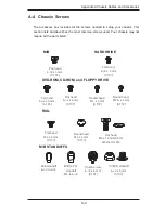
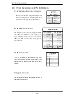
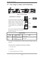
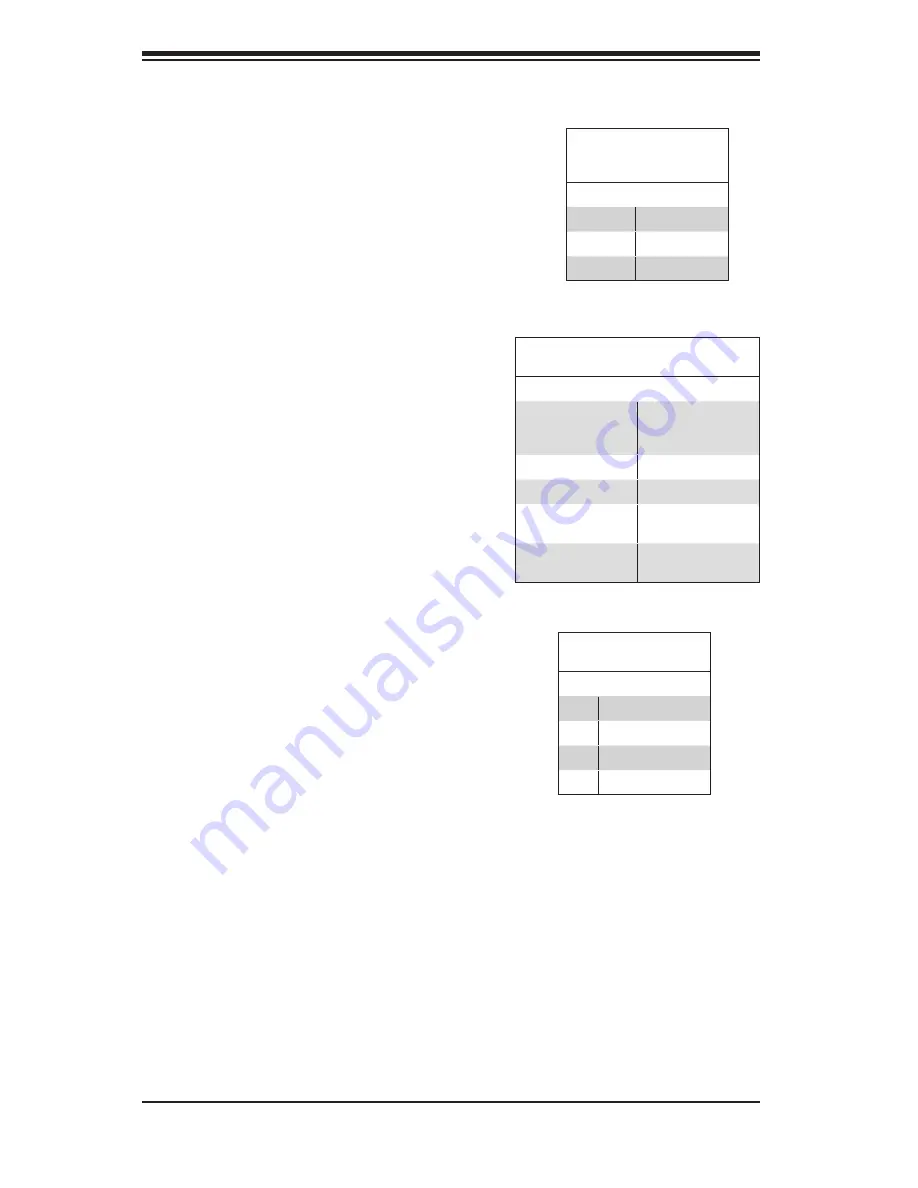
#7 Upgrade Connector
The upgrade connector, designated JP69 is a
firmware upgrade port.
#5 - #6 I
2
C Connectors
The I
2
C connectors, designated JP37 and
JP95, are used to monitor HDD activity and
status. See the table on the right for pin defi
-
nitions.
I
2
C Connector
Pin Definitions
Pin# Definition
1
Data
2
Ground
3
Clock
4
No Connection
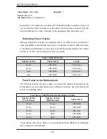
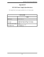
Backplane
Main Power
4-Pin Connector
Pin# Definition
1
+12V
2 and 3
Ground
4
+5V
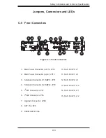
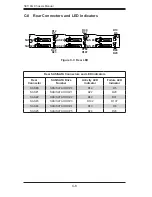
C-6 Front Connector and Pin
Definitions
#1 - #2 Backplane Main Power Connectors
The 4-pin connectors, designated JP10 and
JP13 provide power to the backplane. See
the table on the right for pin definitions.
#3 - #4 Sideband Connectors
The sideband connectors are designated JP51
and JP53. For SES-2 to work properly, an
8-pin sideband cable must be connected to
JP51 and JP53. See the table to the right for
pin definitions.
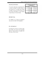
Sideband Connector
Pin # Definition
Pin # Definition
2
Backplane
Addressing
(SB5)
1
Controller
ID (SB6)
4
Reset (SB4)
3
GND (SB2)
6
GND (SB3)
5
SDA (SB1)
8
Backplane
ID (SB7)
7
SCL (SB0)
10
No Connec-
tion
9
No Connec-
tion
Summary of Contents for SC118G-R1400B
Page 1: ...SC118G Chassis Series SC118G R1400B USER S MANUAL 1 0a SUPER ...
Page 8: ...SC118G Chassis Manual viii Notes ...
Page 40: ...SC118G Chassis Manual 5 18 Notes ...
Page 50: ...SC118G Chassis Manual 6 10 Notes ...
Page 54: ...SC118G Chassis Manual A 4 Notes ...
Page 56: ...SC118G Chassis Manual B 2 Notes ...
Page 65: ...C 9 Safety Information and Technical Specifications Notes ...