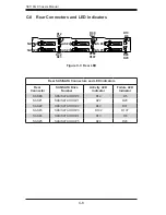
C-6
SC118G Chassis Manual
MH4
MH3
MH2
MH1
BAR CODE
DESIGNED IN USA
C102
C100
Y1
JP18
1
3
JP84
1
3
JP35
1
3
U18
U25
U31
U26
U1
JP26
JP10
1
4
JP13
1
4
BZ1
+
C142
7
J10
7
J7
7
J8
J9
7
J12
7
J11
JP51
1
2
7
8
JP53
1
2
8
64
49
33
16
1
JP69
1
2
5
6
U24
JP37
JP95
D3
A
C
+
C6
+
C5
+
C47
+
C44
+
C139
RRRRRRR
RRR
UPER
S
UPER
S
UPER
S
UPER
S
UPER
S
UPER
S
UPER
S
UPER
S
UPER
S
UPER
S
UPER
S
UPER
S
UPER
S
UPER
S
UPER
S
UPER
S
UPER
S
R
UPER
S
TEL:408-503-8000 FAX:408-503-8008
www.supermicro.com
DESIGNED BY SUPERMICRO U.S.A.
SAN JOSE,CA 95131
PROJECT NAME:
2009 11 24
DATE:
DESINGER:
LAYOUT TEAM 1
ARE IN INCHES
DECIMAL
TOLERANCES
.1
.03
.010
X
XX
XXX
UNLESS OTHERWISE
SPECIFIED DIMENSIONS
ANGLE
30
MACH FINISH
BPN-SAS118TQ
REV: 1.01
BUZZER
D3:ALARM
SAS #5
SAS #4
SAS #3
SAS #2
SAS #1
SAS #0
SB#2
I2C#2
JP18
BUZZER RST
1-2:RST
2-3:NO RST
Sara Cui
1-2:SGPIO
JP84
MODE SEL
2-3:I2C
1-2:RST
JP35
MG9072 RST
2-3:NO RST
UPGRADE
I2C#1
SB#1
+5V
GND
+12V
+12V
GND
+5V
PRIMARY-SIDE
SILKSCREEN
ACT IN
REV 1.01
BPN-SAS118TQ
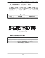
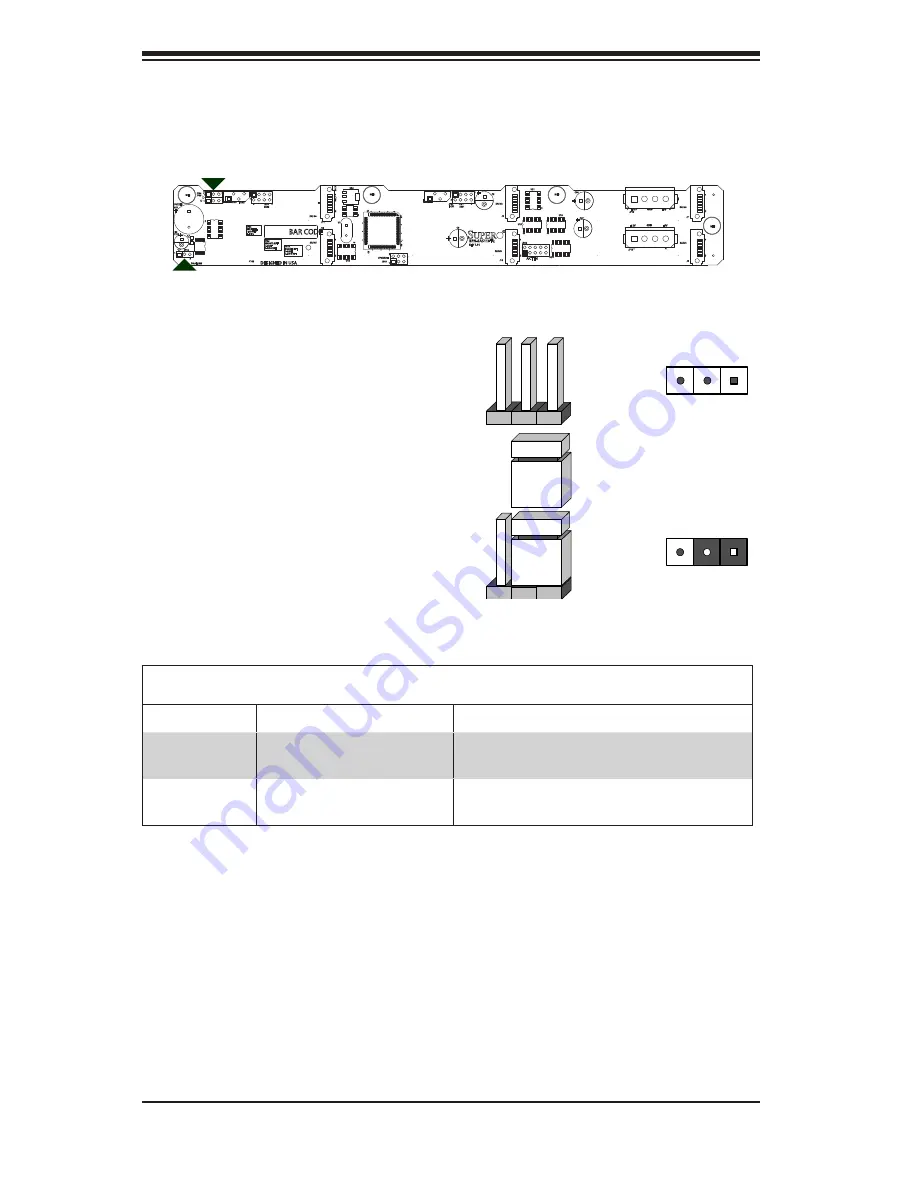
C-7 Front Jumper
Locations and Pin Definitions
JP18
JP35
JP84
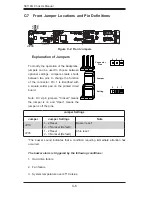
Explanation of Jumpers
To modify the operation of the backplane,
jumpers can be used to choose between
optional settings. Jumpers create shorts
between two pins to change the function
of the connector. Pin 1 is identified with
a square solder pad on the printed circuit
board.
Note: On 2-pin jumpers, "Closed" means
the jumper is on and "Open" means the
jumper is off the pins.
Connector
Pins
Jumper
Setting
3 2 1
3 2 1
Jumper Settings
Jumper
Jumper Settings
Note
JP18
1 - 2 Reset
2 - 3 No reset (Default)
Buzzer reset*
JP35
1 - 2 Reset
2 - 3 No reset (Default)
Chip reset
Figure C-2: Front Jumpers
*The buzzer sound indicates that a condition requiring immediate attention has
occurred.
The buzzer alarm is triggered by the following conditions:
1. Hard drive failure
2. Fan failure
3. System temperature over 45º Celsius.
Summary of Contents for SC118G-R1400B
Page 1: ...SC118G Chassis Series SC118G R1400B USER S MANUAL 1 0a SUPER ...
Page 8: ...SC118G Chassis Manual viii Notes ...
Page 40: ...SC118G Chassis Manual 5 18 Notes ...
Page 50: ...SC118G Chassis Manual 6 10 Notes ...
Page 54: ...SC118G Chassis Manual A 4 Notes ...
Page 56: ...SC118G Chassis Manual B 2 Notes ...
Page 65: ...C 9 Safety Information and Technical Specifications Notes ...

