C-5
Appendix C BPN-SAS-119XTQ Backplane Specifications
+
+
+
+
+
+
+
+
1
3
1
4
1
4
1
2
5
6
1
2
7
8
1
2
7
8
7
7
7
7
7
7
7
7
16
17
32
33
48
49
64
DESIGNED IN USA
+5V
+12V
+12V
GND
+5V
REV 1.00
BPN-SAS-119XTQ
Y1
MH5
MH4
MH1
MH2
MH3
R111
C7
C8
C5
C47
C45
C30
JP35
JP13
JP10
JP69
JP53
JP51
J14
J17
J7
J8
J12
J9
J10
J11
U28
#7
#6
#5
SB#1
SB#2
UPGRADE
1-2:RST
JP35
MG9072 RST
2-3:NO RST
#3
#4
#2
#1
#0
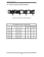
C-7 Front Jumper Locations and Pin Settings
JP35
Explanation of Jumpers
To modify the operation of the backplane,
jumpers can be used to choose between
optional settings. Jumpers create shorts
between two pins to change the function
of the connector. Pin 1 is identified with
a square solder pad on the printed circuit
board.
Note: On 2-pin jumpers, "Closed" means
the jumper is on and "Open" means the
jumper is off the pins.
Connector
Pins
Jumper
Setting
3 2 1
3 2 1
Figure C-2: Front Jumpers
Jumper Settings
Jumper
Jumper Settings
Note
JP35
Pins 1 - 2 Reset
Pins 2 - 3 No reset (Default)
Chip reset
Summary of Contents for SC119XTQ-BR700WB
Page 1: ...SC119X Chassis Series SC119XTQ BR700WB USER S MANUAL 1 0 SUPER...
Page 8: ...SC119X Chassis Manual viii Notes...
Page 42: ...SC119X Chassis Manual 4 6 Notes...
Page 70: ...SC119X Chassis Manual A 4 Notes...
Page 72: ...SC119X Chassis Manual B 2 Notes...
Page 79: ...C 7 Appendix C BPN SAS 119XTQ Backplane Specifications Notes...


