background image

Chassis SC213X User's Manual

30

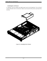
Installing the Air Shroud

If necessary, move any cables that interfere with the air shroud placement. The air shroud 

fits just behind the fans in the fan rack. Slide the air shroud into the grooves just behind the 

fan rack. 

Figure 3-8. Installing the Air Shroud

Summary of Contents for SC213X Series

Page 1: ...USER S MANUAL Revision 1 0 SC213X Chassis Models SC213XAC R1K05LP...

Page 2: ...s operated in a commercial environment This equipment generates uses and can radiate radio frequency energy and if not installed and used in accordance with the manufacturer s instruction manual may c...

Page 3: ...n supported parts and configurations http www supermicro com Notes Information on this and other chassis is available on the Supermicro website Supermicro product manuals http www supermicro com suppo...

Page 4: ...tup Location 12 Rack Precautions 12 Server Precautions 13 Rack Mounting Considerations 13 Ambient Operating Temperature 13 Airflow 13 Mechanical Loading 13 Circuit Overloading 13 Reliable Ground 14 2...

Page 5: ...ing 29 Installing the Air Shroud 30 Checking the Server Air Flow 31 Overheating 31 Power Supply 32 Power Supply LEDs 32 Installing the Motherboard 34 Permanent and Optional Standoffs 34 Replacing the...

Page 6: ...e Address Super Micro Computer B V Het Sterrenbeeld 28 5215 ML s Hertogenbosch The Netherlands Tel 31 0 73 6400390 Fax 31 0 73 6416525 Email sales supermicro nl General Information support supermicro...

Page 7: ...wer supply for outstanding power savings and specially designed optimized cooling 1 1 Overview This chapter provides a brief outline of the functions and features Models are listed below SC213X Chassi...

Page 8: ...DVD drive Power Two redundant 800 1000 W modules 80Plus Titanium level Cooling Four 8 cm hot swap PWM 7k fans with enhanced cooling design Form Factor 2U rackmount slide mounting rails Motherboard Sup...

Page 9: ...k drive activity 5 NIC LED Indicates network activity on the LAN when flashing 6 NIC LED Indicates network activity on the LAN when flashing 7 Power Fail Indicates one of the power supply modules has...

Page 10: ...drive carriers display status lights Figure 1 2 Front View Control Panel Chassis Rear The illustration below shows the features included on the rear of the chassis Power supply modules display status...

Page 11: ...be prominently displayed on the outside of the shipping carton and mailed prepaid or hand carried Shipping and handling charges will be applied for all orders that must be mailed when service is compl...

Page 12: ...is product should be installed only in a Restricted Access Location dedicated equipment rooms service closets etc This product is not suitable for use with visual display workplace devices acccording...

Page 13: ...bient Operating Temperature If installed in a closed or multi unit rack assembly the ambient operating temperature of the rack environment may be greater than the room s ambient temperature Therefore...

Page 14: ...em remains stable The following guidelines are provided to ensure your safety This unit should be mounted at the bottom of the rack if it is the only unit in the rack When mounting this unit in a part...

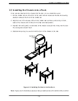
Page 15: ...to the rack and a middle rail which extends from the outer rail These assemblies are specifically designed for the left and right side of the chassis looking from the front and so labeled Locking Tab...

Page 16: ...inner rail has a locking latch that prevents the server from coming completely out of the rack when when the chassis is pulled out for servicing 1 Pull the inner rail out of the outer rail until it is...

Page 17: ...the chassis aligning the mushroom pins on the side of the chassis with the holes in the inner rail 3 Slide the inner rail forward toward the front of the chassis and under the mushroom pins until the...

Page 18: ...ting the length until it just fits within the posts of the rack 5 Hang the hooks of the rear section of the outer rail onto the square holes on the rear of the rack Take care that the proper holes are...

Page 19: ...middle rail out of the front of the outer rail and make sure that the ball bearing shuttle is locked at the front of the middle rail 2 Align the rear of the chassis rails with the middle rails and the...

Page 20: ...evious procedure Releasing the Inner Rail Caution The loaded chassis is heavy Mount or remove the chassis using sufficient personel and or a lift You can also lighten the chassis by removing the drive...

Page 21: ...d from the system 3 1 Removing Power Use the following procedure to ensure that power has been removed from the system This step is necessary when removing or installing non hot swap components or whe...

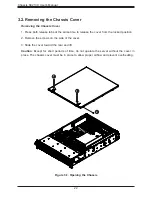
Page 22: ...the cover from the locked position 2 Remove the screws on the side of the cover 3 Slide the cover toward the rear and lift Caution Except for short periods of time do not operate the server without t...

Page 23: ...ivity indicator and a status indicator In RAID configurations the status indicator lights to indicate the status of the drive In non RAID configurations the status indicator remains off See the table...

Page 24: ...Carrier Installing Drives Removing a Hard Drive Carrier from the Bay 1 Press the release button on the drive carrier This extends the drive carrier handle 2 Hold the handle to pull the carrier out of...

Page 25: ...nstallation 2 Secure the drive to the carrier with M3 flat head screws included in the HDD bag of your accessory box Note that the screws used to secure the dummy drive to the tray cannot be used to s...

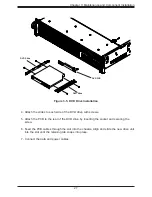
Page 26: ...nd remove the chassis cover 2 Reach inside the chassis and push out the slide tray It has a release tab on its rear left corner that should be pressed to the right The slide tray may hold COM and USB...

Page 27: ...e slides to each side of the DVD drive with screws 5 Attach the PCB to the rear of the DVD drive by inserting the socket and securing the screw 6 Feed the PCB cables through the slot into the chassis...

Page 28: ...s described in Section 3 1 and remove the cover 2 In the rear of the chassis remove the blank shield that is pre installed covering the expansion slot 3 Slide the expansion card into the expansion slo...

Page 29: ...ystem Fan 1 Identify the failed fan using IPMI Otherwise while the system is running examine the fans to determine which one has failed 2 Press the release tab and pull the fan out of the housing Caut...

Page 30: ...he Air Shroud If necessary move any cables that interfere with the air shroud placement The air shroud fits just behind the fans in the fan rack Slide the air shroud into the grooves just behind the f...

Page 31: ...chassis Pull all excess cabling out of the airflow path or use shorter cables The control panel LEDs display system heat status See Control Panel in Chapter 1 for details Overheating There are severa...

Page 32: ...40v Power Supply LEDs On the rear of the power supply module an LED displays the status Solid Green When illuminated indicates that the power supply is on Solid Amber When illuminated indicates the po...

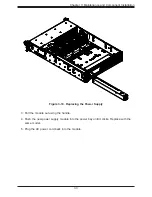
Page 33: ...t Installation 3 Pull the module out using the handle 4 Push the new power supply module into the power bay until it clicks Replace with the same model 5 Plug the AC power cord back into the module Fi...

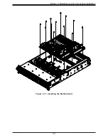
Page 34: ...the holes provided on the floor of the chassis Installing the Motherboard 1 Be sure the power cord is removed 2 Install the I O shield into the space provided at the rear of the chassis 3 If necessar...

Page 35: ...35 Chapter 3 Maintenance and Component Installation Figure 3 11 Installing the Motherboard...

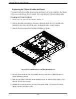
Page 36: ...he power distributor board from the motherboard backplane and other components Also remove both power supply modules 3 Remove the screws securing the power distributor as shown Figure 3 12 Installing...

Page 37: ...ications This appendix lists power supply specifications for your chassis system 800 1000 W MFR Part PWS 1K05A 1R AC Input 100 127Vac 9 7 5A 50 60Hz 200 240Vac 6 5A 50 60Hz DC Output 12 volts Max 66 7...

Page 38: ...sistance Only certified technicians should attempt to install or configure components Read this appendix in its entirety before installing or configuring components in the Supermicro chassis These war...

Page 39: ...o considere los riesgos de la corriente el ctrica y familiar cese con los procedimientos est ndar de prevenci n de accidentes Al final de cada advertencia encontrar el n mero que le ayudar a encontrar...

Page 40: ...ient u zich bewust te zijn van de bij een elektrische installatie betrokken risico s en dient u op de hoogte te zijn van de standaard procedures om ongelukken te voorkomen Gebruik de nummers aan het e...

Page 41: ...mentaci n Attention Avant de brancher le syst me sur la source d alimentation consulter les directives d installation Circuit Breaker Waarschuwing Raadpleeg de installatie instructies voordat u het sy...

Page 42: ...el edificio Aseg rese de que el dispositivo de protecci n no sea superior a 250 V 20 A Attention Pour ce qui est de la protection contre les courts circuits surtension ce produit d pend de l installat...

Page 43: ...e energ a y del cable el ctrico quitado de los m dulos de fuente de alimentaci n antes de tener acceso el interior del chasis para instalar o para quitar componentes de sistema Attention Le syst me do...

Page 44: ...aangesloten op de voeding en van de behuizing te verwijderen Equipment Installation Warning Only trained and qualified personnel should be allowed to install replace or service this equipment Warnung...

Page 45: ...tention Il est vivement recommand de confier l installation le remplacement et la maintenance de ces quipements des personnels qualifi s et exp riment s Warning This unit is intended for installation...

Page 46: ...a de estas reas mediante la utilizaci n de una herramienta especial cerradura con llave u otro medio de seguridad Attention Cet appareil doit tre install e dans des zones d acc s r serv s L acc s une...

Page 47: ...mblable ou quivalent recommand e par le fabricant Jeter les piles usag es conform ment aux instructions du fabricant Advertencia Existe peligro de explosi n si la bater a se reemplaza de manera incorr...

Page 48: ...volen wordt Gebruikte batterijen dienen overeenkomstig fabrieksvoorschriften afgevoerd te worden Redundant Power Supplies Warning This unit might have more than one power supply connection All connec...

Page 49: ...mloos te maken Advertencia Puede que esta unidad tenga m s de una conexi n para fuentes de alimentaci n Para cortar por completo el suministro de energ a deben desconectarse todas las conexiones Atten...

Page 50: ...encia Cuando el sistema est en funcionamiento el voltaje del plano trasero es peligroso Tenga cuidado cuando lo revise Attention Lorsque le syst me est en fonctionnement des tensions lectriques circul...

Page 51: ...umplir con las normas de electricidad locales y nacionales Backplane Waarschuwing Een gevaarlijke spanning of energie is aanwezig op de backplane wanneer het systeem in gebruik is Voorzichtigheid is g...

Page 52: ...lektriciteitsvoorschriften Warnung Die Entsorgung dieses Produkts sollte gem allen Bestimmungen und Gesetzen des Landes erfolgen Warning Ultimate disposal of this product should be handled according t...

Page 53: ...recyclage de ce produit sont g n ralement soumis des lois et ou directives de respect de l environnement Renseignez vous aupr s de l organisme comp tent Hot Swap Fan Warning Warning Hazardous moving...

Page 54: ...nilladores y todos los objetos lejos de las aberturas del ventilador Attention Pieces mobiles dangereuses Se tenir a l ecart des lames du ventilateur Il est possible que les ventilateurs soient toujou...

Page 55: ...tadores de CA La utilizaci n de otros cables y adaptadores podr a ocasionar un mal funcionamiento o un incendio Aparatos El ctricos y la Ley de Seguridad del Material proh be el uso de UL o CSA cables...

Page 56: ...areils lectriques que les produits d sign s par Supermicro seulement AC AC UL CSA UL CSA UL CSA Supermicro UL CSA AC Electrical Appliance and Material Safety Law UL CSA UL CSA Waarschuwing Bij het ins...

Page 57: ...57 Appendix B Standardized Warning Statements Notes...

Page 58: ...touching their pins Put the backplane and peripherals back into their antistatic bags when not in use General Safety Guidelines Always disconnect power cables before installing or removing any compone...

Page 59: ...C2 D1 D2 CG2 B7 B8 C8 A7 C7 D7 D8 A8 PRESS FIT CG3 CG4 A1 A2 CG1 B1 B2 C1 C2 D1 D2 CG2 B7 B8 C8 A7 C7 D7 D8 A8 PRESS FIT CG3 CG4 3 2 1 1 2 3 BAR CODE DESIGNED IN USA 44 34 11 12 22 23 33 Q42 C27 JP27...

Page 60: ...The 4 pin connectors designated JP3 JP4 JP5 and JP6 provide power to the backplane See the table on the right for pin definitions 3 6 SAS IN Ports Sideband included The SAS ports are used to connect t...

Page 61: ...2 3 NO RESET 1 2 RESET ATMEL 1 RESET J21 UPGRADE 2 UPGRADE 1 SAS IN 0 3 SAS IN 4 7 SAS IN 8 11 SAS IN 12 15 Jumper Locations and Pin Definitions Explanation of Jumpers To modify the operation of the...

Page 62: ...P1 P15 S8 S14 S1 S7 P1 P15 S8 S14 C15 C21 C3 C9 C12 C18 C24 C6 C14 C17 C2 C20 C23 C5 C8 C11 R1 R2 R3 R4 Q44 Q39 LED3 LED8 LED2 LED5 LED1 LED4 LED6 LED7 LED11 LED9 LED13 LED16 LED10 LED12 LED14 LED15...

Reviews: