SC510 Chassis Manual
5-8
A
1
B
C
D
E
F
G
H
I
J
K
L
M
2
3
4
5
6
7
8
9
10
DESIGN /
³]-p :
MODEL NO./
¾÷«¬ :
SIZE/¹Ï®Ø
APPROVED /
¼ f®Ö :
DRAWN /
ø¹Ï
:
MATERIAL /
§÷½è :
UNIT /
³æ¦ì
:
FINISH /
ªí-±³
B¸Ì :
DATE /
¤é´Á
:
DATE /
¤é´Á:
DATE /
¤é´Á:
TITLE /
«~¦W :
PART NO. /
®Æ¸¹ :
Ablecom Technology Inc.
A
BLEC
DWG NO. /
¹Ï¸¹
:
¤j˚T¬ì§ÞªÑ¥÷¦³--¤½¥
q
THE 3RD PROJECTION
²Ä¤T¨¤ªk
M
R E V I S I O N
S /
-×-q
REV
ª©¥»
DESCRIPTION
±Ô-z
LOCATION
¦ì¸
m
DRAWN
-קïªÌ
DATE
¤é´Á
SC510_SYSTEM_ASSY
A0
*
SCALE /
¤ñ¨Ò :
1:1
SHEET
1 OF 1
SC510
*
SHO
13-Nov-07
See Note.
SHO
13-Nov-07
MM
*
REV.
ª©¥» 1
RANGE
½ d³ò
TOLERANCE
¤½®t
X.xx
± 0.10
X.x
± 0.25
X
± 1.00
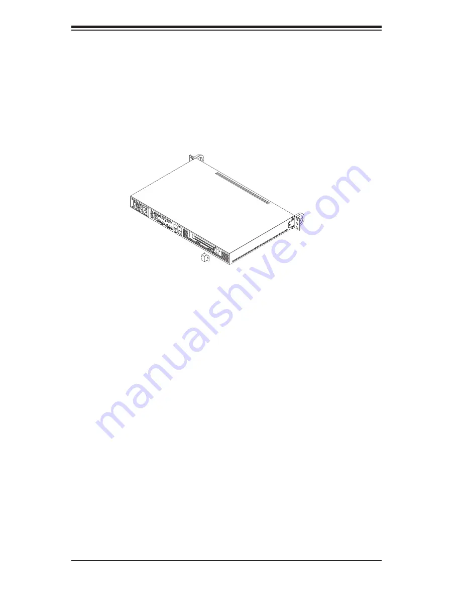
Figure 5-7. Replace the Expansion Card Clip
5. Insert the assembled expansion card and riser card into the expansion slot
inside the chassis, carefully aligning the plate of the expansion card with the
openings in the back of the chassis.
6. Replace the expansion card clip and screw it onto the chassis to hold the
expansion card in place.
Summary of Contents for SC510 Series
Page 10: ...SC510 Chassis Manual 1 4 Notes ...
Page 30: ...2 20 SC510 User s Manual Notes ...


