


115
Appendix E: M35TQ Mobile Rack Specifications
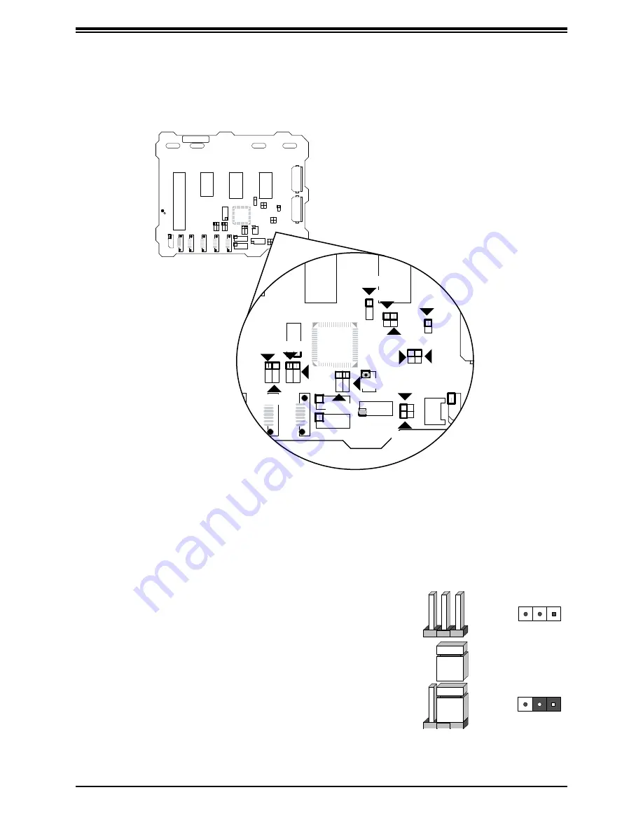
E.8 Front Jumper Locations and Pin Definitions
REV 1.0
1
REV 1.01
SASM35TQSASM35TQ
RR
SS
UPERUPER
REV 1.0
1
REV 1.01
SASM35TQ
SASM35TQ
R
R
S
S
UPER
UPER
JP37
JP34
JP36
JP33
JP42
JP43
JP62
JP38
JP18
JP50
JP41
JP40
JP29
JP61
Figure E-2. Front Jumpers
Explanation of Jumpers
To modify the operation of the mobile rack, jumpers can be
used to choose between optional settings. Jumpers create
shorts between two pins to change the function of the
connector. Pin 1 is identified with a square solder pad on
the printed circuit board. Note: On two pin jumpers, "Closed"
means the jumper is on and "Open" means the jumper is
off the pins.
Connector
Pins
Jumper
Setting
3 2 1
3 2 1


