background image

1-7

Chapter 1: Introduction  

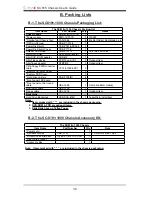
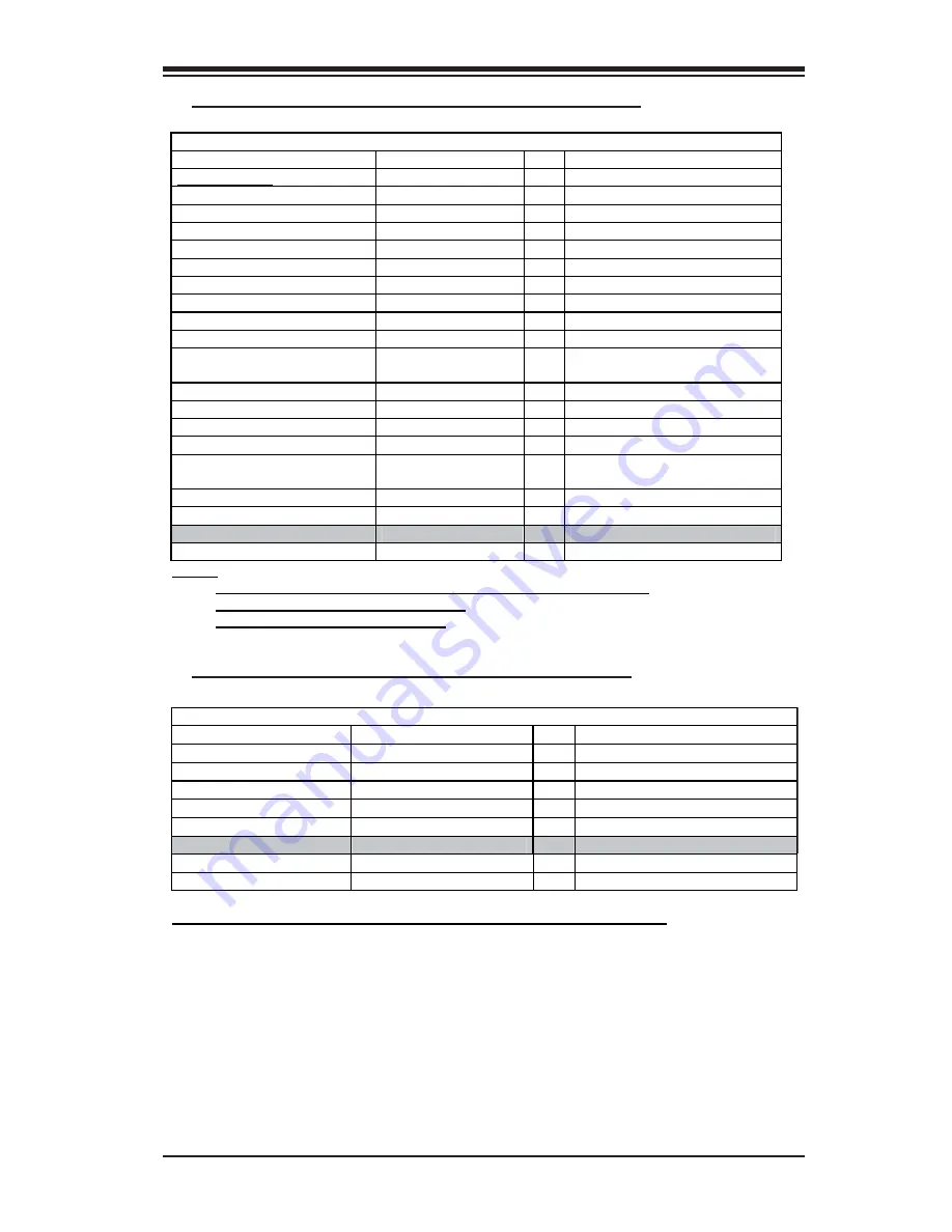
B-3. The SC818-1000 Chassis Packaging List:

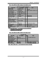
B-4. The SC818-1000 Chassis Accessory Kit:

The SC818 1000 Chassis Packing List 

Item Name 

Part Number 

Q'ty

Notes 

Chassis body

CSE-818 1000 

1  

*Power supply  

PWS-1K01-1R 

1 1000W 

*Cooling fan (Chassis fan) 

FAN-0086 

6 40x56  (Nidec) Dual blade 3 pin

*CPU Air Shroud 

CSE-PT-0128 

1  

Power Distributor 

CSE-PT818-PD284 

1  

Power Distributor Cover 

CSE-PT126 

1  

Slim DVD-ROM 

DVM-PNSC-824(B) 

1  

Slim DVD -ROM adapter 

SCD812 

1   

Slim Floppy device 

FPD-Teac-S (B) 

0 Optional Item 

Slim floppy adapter 

SFBP812 

0 Optional Item 

CD & floppy PWR converter 
cable  

07-01-813904-XX1 

2  

*Dummy CD-ROM Cover 


0  

*Dummy FDD Cover 


1  

*Hard drive carriers 

CSE-PT39(B) 

4   

*Front panel LED board 


1   

*Front panel control round 
cable 

CBL-0049 

1 Flat cable 54cm (cable) 

DVD-ROM cable 

CBL-0139 

1  

Floppy cable 

CBL-0078 

1 Optional Item 

Backplane

Hard Drive Backplane 


1 SuperMicro install item 

Notes:

1.  Items marked with “ * ”  are included in the chassis packaging.
2.  DVD-ROM & FDD are optional items.
3.  Slide Rails have no Teflon Tapes.

The SC818-1000 

Item Name 

Part Number 

Q'ty

Note 

*Power cord 


1   

*Rail accessories 

CSE-PT51 

1 1U Rail W/Teflon Tape 

*Screw and tie wrap kits 

(A) B0-01-814O01-XXA 

1   

*Riser card bracket 


1   

*Accessory Box 


1   

Hard Drive Backplane 
SATA cable 

CBL-0058 

4

SuperMicro install item 

SATA LED cable 

CBL-0056 

1

SuperMicro install item 

Note:   Items marked with “ * ”  are included in the chassis packaging.

Summary of Contents for SC818

Page 1: ...Rev 1 0 SUPER The SC818 Chassis Series User Guide ...

Page 2: ...USE THIS PRODUCT OR DOCUMENTATION EVEN IF ADVISED OF THE POSSIBILITY OF SUCH DAMAGES IN PARTICULAR THE VENDOR SHALL NOT HAVE LIABILITY FOR ANY HARDWARE SOFTWARE OR DATA STORED OR USED WITH THE PRODUCT INCLUDING THE COSTS OF REPAIRING REPLACING INTEGRATING INSTALLING OR RECOVERING SUCH HARDWARE SOFTWARE OR DATA Any disputes arising between manufacturer and customer shall be governed by the laws of ...

Page 3: ... 1 A Removing the Top Cover of the SC818 Chassis 2 1 B Removing the Riser Card Bracket from the Chassis 2 2 C Installing the Motherboard into the Chassis 2 3 D Installing the Chipset Air Shroud into the Chassis 2 5 E Installing the CPU Air Shroud into the Chassis 2 6 F Accessing the Hard Disk Drive Tray and Installing a Hard Drive 2 7 G Rail Installation 2 8 H Installing the Chassis into the Rack ...

Page 4: ...nents and printed circuit boards PCBs in their antistatic bags until ready for use Touch a grounded metal object before removing chassis components or the motherboard from the antistatic bag Do not let components or PCBs come into contact with your clothing which may retain a charge even if you are wearing a wrist strap Handle a motherboard by its edges only do not touch its components peripheral ...

Page 5: ...inside the chassis 2 Make sure that all cables are properly connected to the connectors and ports 3 Use the original screws or fasteners to install the covers to the chassis 4 Be sure to lock to the chassis or the system to prevent unauthorized access 5 Please follow the procedures listed in Chapter 2 to install or remove components to or from the SC818 A 5 An Important Note to the User All images...

Page 6: ...tem Slim floppy adapter SFBP812 0 Optional Item CD floppy PWR converter cable 07 01 813904 XX1 2 Dummy CD ROM Cover 0 Dummy FDD Cover 1 Hard drive carriers CSE PT39 B 4 Front panel LED board 1 Front panel control round cable CBL 0049 1 Flat cable 54cm cable DVD ROM cable CBL 0139 1 Floppy cable CBL 0078 1 Optional Item Backplane Hard Drive Backplane CSE SAS 818S 1 SuperMicro install item Notes 1 I...

Page 7: ...813904 XX1 2 Dummy CD ROM Cover 0 Dummy FDD Cover 1 Hard drive carriers CSE PT39 B 4 Front panel LED board 1 Front panel control round cable CBL 0049 1 Flat cable 54cm cable DVD ROM cable CBL 0139 1 Floppy cable CBL 0078 1 Optional Item Backplane Hard Drive Backplane 1 SuperMicro install item Notes 1 Items marked with are included in the chassis packaging 2 DVD ROM FDD are optional items 3 Slide R...

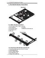
Page 8: ...nel See C 2 below 2 Power Module 6 Chipset 3 Power Back Plane 7 DDR Memory Modules 8 4 Fan Modules 6 5 CPUs 4 Front View C 2 Front Panel LED Indicators and IO Ports 1 Front Panel LED Indicators See C 3 below 2 CD ROM DVD ROM 3 Power Supply Module 4 Hard Disk Drives 3 5 Floppy Drive optional 1 2 3 4 4 4 1 2 3 4 5 6 6 7 5 ...

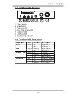
Page 9: ...LAN Port1 LED 6 LAN Port2 LED 7 Overheat Fan Fail LED C 4 Front Panel LED Descriptions LED Button Color Condition Description Green On System On Power Off System Off Amber Blinking HDD Activity HDD Off No Activity Green On Linked Blinking LAN Activity LAN1 LAN2 Off Disconnected Red On System Overheat Off System Normal Overheat Blinking Fan Failure ...

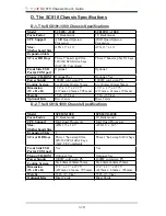
Page 10: ...40mmx56mm Dimension W x H x D 17 2 x 1 7 x 27 75 437mm x 43mm x 705 mm 17 2 x 1 7 x 27 75 437mm x 43mm x 705mm Weight 35 lb 15 9 kg 35 lb 15 9 kg Optional Kits Riser Cards Riser Cards Model SC818S 1000 SC818TQ 1000 Form Factor 1U Rackmount 1U Rackmount CPU Support Intel Quad Processors Intel Quad Processors Max Motherboard Size ATX 16 x 14 5 ATX 16 x 14 5 Expansion Slots 1 1 SCA or HD Bays Three 1...

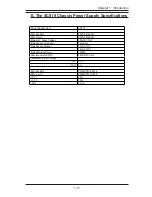
Page 11: ...el PWS 1K01 1R Mfr Part PWS 1K01 1R Rated AC Input Voltage 100 240 VAC Rated Input Frequency 50 60 Hz Rated Input Current 15A 115V 10A 230V Rated Output Power 1000W Maximum rated BTU 4400 BTUs Hr Nominal Output Voltage 12V 83A 5Vsb 4A Mfr Model PDB PT818 8824 Mfr Part PDB PT818 8824 5V 20A 3 3V 20A 12V 0 6A ...

Page 12: ...SC818 Chassis User s Guide 1 12 Notes ...

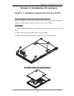
Page 13: ...y components replacing chassis fans or accessing the mother board you will first need to remove the top cove from the chassis Procedures 1 Using a Philips screw driver remove two screws from the top cover as shown below 2 Unlock and remove the thumb screw from the chassis 3 Press the release tabs and slide the top cover out from the chassis The SC818 w the Top Cover Removed 1 2 3 1 ...

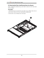
Page 14: ...alling the motherboard you will need to remove the riser card bracket from the chassis Procedures 1 After the top cover is removed from the chassis using a Philips screw driver to remove the two screws on the riser card bracket as shown below 2 Remove the riser card bracket from the chassis 1 2 ...

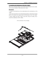
Page 15: ...hassis Procedures 1 Locate the mounting holes on the motherboard and the mounting holes on the chassis 2 Align the mounting holes on the motherboard against the corresponding mounting holes on the chassis Once aligned place the motherboard on top of the chassis 3 Using a Philips screw driver install a 6 32 screw into each mounting hole to secure the motherboard onto the chassis To be continued on ...

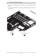
Page 16: ...er s Guide 2 4 4 Connect power cables to the power connectors on the motherboard as shown below 5 Connect fan cables to the fan headers on the motherboard as shown in the picture below Power Connectors Fan Headers 4 5 ...

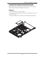
Page 17: ...he chassis you will need to install the chipset air shroud to prevent the chipset from overheat Procedures 1 Align the chipset air shroud with the chipset 2 Once aligned secure the chipset air shroud into the chassis with a 6 32 x 13L screw as shown below 3 Connect fan cables to the fan headers on the motherboard as shown below 2 3 ...

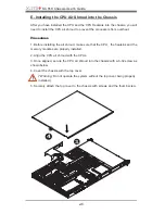
Page 18: ...efore installing the air shroud make sure that the CPU the heatsink and the memory modules are properly installed 2 Align the CPU air shroud with the CPUs 3 Once aligned secure the CPU air shroud into the chassis with a 6 32 screw as shown below 4 Cover the chassis with the top cover Warning Do not operate the system without the top cover being properly installed 5 Securely attach the top cover to...

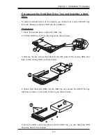
Page 19: ...release tab to unlock the HDD tray 2 Pull the HDD tray out from the chassis as shown below 3 Remove the two screws that attach to the both sides of the dummy HDD and take out the dummy HDD as shown below 4 Slide a hard drive disk HDD into the HDD tray and secure the HDD to the tray with three screws on each side of the tray as shown below 5 Once the HDD is securely placed into the HDD tray you can...

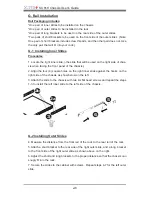
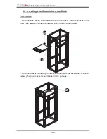
Page 20: ...acing the front panel of the chassis 2 Align the four 4 square holes on the right inner slide against the hooks on the right side of the chassis as show below on the left 3 Attach the slide to the chassis with two M4 flat head screws and repeat the steps 1 3 to install the left inner slide to the left side of the chassis G 2 Installing Outer Slides 4 Measure the distance from the front rail of the ...

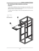
Page 21: ...have installed the short and long brackets to the outer slides you are ready to install the whole slide assemblies outer slides with short and long brackets attached to the rack See the previous page 2 Use M5 screws and washers to secure the slide assemblies into the rack as shown below 2 2 1b M5 Screw Washer ...

Page 22: ... the inner slides which are attached to the chassis into the grooves of the outer slide assemblies that are installed in the rack as shown below 2 Push the chassis all the way to the back of the outer slide assemblies as shown below The plastic bezel is not included in the package 1a 1b 2 ...

Page 23: ...ify a location and choose Next 7 Click on Browse and choose D drive or wherever Supermicro Setup CD is in 8 Choose Qlogic folder and click on Open 9 System will automatically detect GEM318 and install the drive from this point on or 1 Right click the My Computer icon on your desktop and choose Properties 2 Click on the Hardware tab and click on Device Manager to bring up the list of system devices...

Page 24: ...SC818 Chassis User s Guide 2 12 Notes ...

Page 25: ...Rev 1 0 SUPER SCA818S Backplane USER S GUIDE Aappendix ...

Page 26: ...rs and Jumpers A 5 A 1 Front Jumper Connector Locations A 5 A 2 Front Jumper Connector Descriptions A 5 A 3 Front Jumper Connector Pin Definitions A 5 A 4 Front Overheat Drive Failure LED A 6 A 5 Front Jumper Settings and Pin Definitions A 6 B Rear Connectors and LED Indicators A 7 B 1 Rear Connector LED Indicator Locations A 7 B 2 Rear Connector LED Indicator Descriptions A 7 User s Guide Revision ...

Page 27: ... only do not touch its components peripheral chips memory modules or gold contacts When handling chips or modules avoid touching their pins Put the card and peripherals back into their antistatic bags when not in use General Safety Guidelines Always disconnect power cables before installing or removing any components from the computer including the SCA818S Backplane Disconnect the power cable befo...

Page 28: ...0 JP17 A SCA818S Backplane Main Power J10 Backplane Main Power Connector Pin Definitions C CD ROM Floppy Drive Power Connectors CD ROM FDD Power Connector Pin Definitions You must use the 4 pin power connector J10 marked A on the layout above to provide adequate power supply to the Backplane See the table on the right for pin definitions Pins 1 2 3 4 Definition 12 V Ground 5V Backplane Main PWR 4 pin...

Page 29: ... 15 5 DB P1 39 DB P1 6 DB 0 40 DB 0 7 DB 1 41 DB 1 8 DB 2 42 DB 2 9 DB 3 43 DB 3 10 DB 4 44 DB 4 11 DB 5 45 DB 5 12 DB 6 46 DB 6 13 DB 7 47 DB 7 14 DB P 48 DB P 15 Ground 49 Ground 16 DIFFSENS 50 Ground 17 TERMPWR 51 TERMPWR 18 TERMPWR 52 TERMPWR 19 Reserved 53 Reserved 20 Ground 54 Ground 21 ATN 55 ATN 22 Ground 56 Ground 23 BSY 57 BSY 24 ACK 58 ACK 25 RST 59 RST 26 MSG 60 MSG 27 SEL 61 SEL 28 C ...

Page 30: ...cators and buzzers Note This function is available only when a RAID controller with a RAID set is present and enabled Please refer to the table below for the information on SAF TE LED Indicators SAF TE LED Indicators LED Location Description D4 Front Overheat or Drive Failure red light flashing buzzer on D5 Rear SCA 0 Fail LED red light flashing buzzer on D6 Rear SCA 1 Fail LED red light flashing ...

Page 31: ...ription Definition On Default Buzzer Enable JP17 Off Buzzer Disable On Delay Start SCA 0 Enable JP18 Off Default Delay Start SCA 0 Disable On Remote Start SCA 0 Enable JP20 Off Default Remote Start SCA 0 Disable On Delay Start SCA 1 Enable JP22 Off Default Delay Start SCA 1 Disable On Remote Start SCA 1 Enable JP23 Off Default Remote Start SCA 1 Disable On Delay Start SCA 2 Enable JP19 Off Default...

Page 32: ...SCA 1 Activity LED D14 Rear SCA 2 Activity LED D5 Rear SCA 0 Fail LED D6 Rear SCA 1 Fail LED D16 Rear SCA 2 Fail LED Rear View SCA 1 D12 D13 D14 D16 B 2 1 Backplane Rear Connectors B Rear Connectors and LED Indicators B 1 Rear Connector LED Indicator Locations B 2 Connector LED Indicator Descriptions See below for rear connector LED descriptions D5 D6 SCA1 B 2 2 Backplane Rear LED Indicators SCA 0...

Reviews: