C-2
SC825M(B) Chassis Manual
J8
R
S
UPER
#2
J35
LED TEST
RESET J29
JP46
JP51
UPGRADE
SIDEBAND
REV 1.02
BPN-SAS-825MTQ
#1
J10
J9
J7
#0
J8
JP10
J6
+12V
+12V
GND
GND
GND
+5V
+5V
+12V
GND +5V
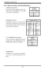
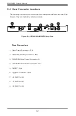
Rear Connectors
1. Main Power Connector: JP10
2. Sideband (SGPIO) Connector: JP51
3. DVD-ROM Drive Power Connector: J9
4. DVD-ROM Drive Power Connector: J10
5. MG9071 Chip
6. Upgrade Connector: JP46
7. J8: SAS Port #0
8. J7: SAS Port #1
9. J6: SAS Port #2
C-4 Rear Connector Locations
The following connectors are on the side of the backplane that faces the rear of the
chassis. They are marked by silkscreen labels.
1
1
1
2
1
7
1
8
1
9
1
3
1
5
1
6
1
4
Figure D-1. BPN-SAS3-825MTQ Rear View
Summary of Contents for SC825M Series
Page 12: ...SC825M B Chassis Manual 1 4 Notes ...
Page 32: ...2 20 SC825MB Chassis Manual Notes ...
Page 62: ...SC825M B Chassis Manual 5 24 Notes ...
Page 72: ...SC825M B Chassis Manual 6 10 Notes ...
Page 74: ...SC825M B Chassis Manual A 2 Notes ...


