5-11
Chapter 5: Chassis Setup and Maintenance
Installing a UIO Card
1. Power down the system and remove the power cord from the back of the
power supply module as described in Section 5-2. Remove the chassis cover
as described in Section 5-3.
2. Release the clamp that secures all four full-height PCI shields (Figure 5-13).
Looking at the rear of the chassis, this clamp is in the right corner. Unscrew
the single screw that secures the clamp and rotate the clamp away from the
shields. Remove the blank PCI shield that is pre-installed covering the expan-
sion slot in the chassis.
3. Place the UIO card horizontally in the rear left area of the chassis bottom and
insert it into the blue UIO slot in the motherboard, while aligning it with slot in
the rear of the chassis.
4. Secure the shield to the rear of the chassis with the lever.
Installing an Expansion Card for a U Model Chassis
1.
If this is the first expansion card, start by locating the
riser card bracket
in your
chassis accessory bag, and one or two riser cards, which are purchased sepa-
rately. One riser card accomodates the full-height expansion cards and another
riser card accomodates the three low profile expansion cards.
2. Power down the system as described in Section 5-2 and remove the cover as
desribed in Section 5-3.
3. Attach the riser card(s) to the riser card bracket using screws. Note that there
are different cards for the right and left side of the bracket.
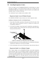
4. Insert the riser card(s) into the motherboard expansion slot(s) while aligning the
riser card bracket with the rear of the chassis. Secure the bracket with screws
(Figure 5-12).
Figure 5-12. Riser Card Bracket


