C-6
SC825 Chassis Manual
1
1
16
32
48
BAR CODE
REV 2.0
SAS825TQ
1
GND
GND
+12V
+5V
GND
GND
+12V
+5V
#2
I C
#1
ACT_IN
JP29:9072 RESET
I C
SIDEBAND #2
SIDEBAND #1
2
2
+ +
+ +
+ +
+ +
+
+
+
+
+
+
1
1
1
16
32
48
GND
GND
+12V
+5V
GND
GND
+12V
+5V
+
+
+
BAR CODE
+
+
+
REV 2.0
SAS825TQ
#2
2
I C
#1
ACT_IN
JP29:9072 RESET
2
I C
SIDEBAND #2
SIDEBAND #1
+ +
+ +
+ +
+ +
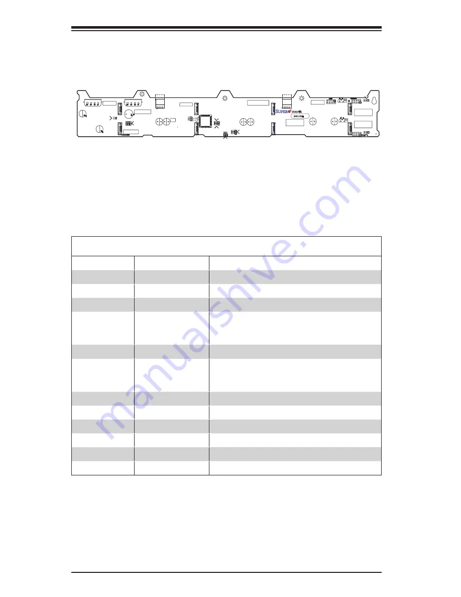
C-6 Front Jumper Locations and Pin Definitions
JP18
JP29
JP38
JP50
JP36
JP33
JP41
JP34
JP42
JP37
JP43
JP40
Front Jumper Locations
I
2
C and SGPIO Modes and Jumper Settings
This backplane can utilize I
2
C or SGPIO. I
2
C is the default mode and can be used
without making changes to your jumpers. The following information details which
jumpers must be configured to use SGPIO Settings or restore your backplane to
I
2
C mode.
I
2
C Setting (Default)
Jumper
Jumper Setting
Note
JP18
Open
Closed: Buzzer Reset (Default)
JP29
Open
Closed: MG9072 Reset (Default)
JP33
2-3
Controller ID #1
JP34
1-2
Backplane ID #1
1-2: ID#0
2-3: ID#1
JP36
2-3
Controller ID #2
JP37
2-3
Backplane ID #2
1-2: ID#0
2-3: ID#1
JP38
On
I
2
C Reset #2
JP40
Off
I
2
C Reset _SDOUT#1
JP41
Off
I
2
C Reset _SDOUT#2
JP42
2-3
I
2
C Backplane ID _SDIN#1
JP43
2-3
I
2
C Backplane ID _SDIN#2
JP50
On
I
2
C Reset #1


