SC826 Chassis Manual
3-2
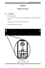
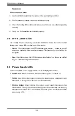
3-3 Control Panel LEDs
There are six LEDs that provide status information about the system.
Power
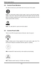
: The main power switch is used to apply or remove power from the power
supply to the server. Turning off system power with this button removes the main
power but maintains standby power. To perform many maintenance tasks, you must
unplug system before servicing.
Reset
: The reset button is used to reboot the system.
NIC2
: Indicates network activity on GLAN2 when flashing.
3-2 Control Panel Buttons
The chassis includes two push-buttons that control power to the system.
Power
: Indicates power is being supplied to the system power supply units. This
LED should normally be illuminated when the system is operating.
HDD
: Indicates IDE channel activity on the hard drive when flashing.
Summary of Contents for SC826 Series
Page 12: ...SC826 Chassis Manual 1 6 Notes ...
Page 56: ...SC826 Chassis Manual 4 18 Figure 4 16 Placing the System Fan in the Chassis 3 5 ...
Page 60: ...SC826 Chassis Manual 4 22 Notes ...
Page 72: ...SC826 Chassis Manual A 4 Notes ...
Page 84: ...C 10 SC826 Chassis Manual Notes ...
Page 94: ...D 10 SC826 Chassis Manual Notes ...
Page 134: ...F 18 SC826 Chassis Manual Notes ...
Page 145: ...G 11 Appendix G Cascading Configurations Notes ...


