4-19
Chapter 4: Chassis Setup and Maintenance
The system has two redundant, hot-swap power supply modules. They automati-
cally sense the input voltage between 100v to 240v, and operate at that voltage.
An amber light on the power supply is illuminated when the power is switched off.
An green light indicates that the power supply is operating.
Replacement units can be ordered directly from Supermicro.
Power Supply
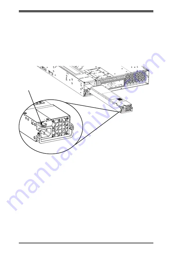
Changing the Power Supply
1. Remove the AC power cord from the back of the power supply module that you
want to replace.
2. Push the release tab on the rear of the power supply.
3. Pull the module out of the power supply bay using the handle.
4. Push the new power supply module into the power bay until it clicks.
5. Plug the AC power cord back into the module and power up the server.
Figure 4-17. Removing the Power Supply
Release Tab
Summary of Contents for SC826 Series
Page 12: ...SC826 Chassis Manual 1 6 Notes ...
Page 56: ...SC826 Chassis Manual 4 18 Figure 4 16 Placing the System Fan in the Chassis 3 5 ...
Page 60: ...SC826 Chassis Manual 4 22 Notes ...
Page 72: ...SC826 Chassis Manual A 4 Notes ...
Page 84: ...C 10 SC826 Chassis Manual Notes ...
Page 94: ...D 10 SC826 Chassis Manual Notes ...
Page 134: ...F 18 SC826 Chassis Manual Notes ...
Page 145: ...G 11 Appendix G Cascading Configurations Notes ...


