E-5
Appendix E: SAS2-826EL Backplane
Specifications
Q9
F1
FANFAIL1
A
C
OVERHEATFAIL1
A
C
5V_LED1
A
C
12V_LED1
A
C
AC
T18
A
C
AC
T17
A
C
+
C367
C366
C365
C353
C352
+
C134
+
C133
+
C132
C121
C120
+
C119
+
EC19
R167
2
1
J16
J19
PRI_J1
PRI_J0
SEC_J0
SEC_J1
BC8
BC518
C157
C395
1
FANFAIL_LED_DISABLE
1
BUZZER_ENB1
1
MDIO1
MDIO2
1
ACTLED1
FAN_MONITOR_DISABLE
1
MH9
MH8
MH7
MH6
MH5
MH4
4
1
FAN1
4
FAN2
1
FAN3
1
8
J18
1
8
5
Y
E
20
R
K
10
15
AE
25
28
AH
5
E
20
R
K
10
15
AE
25
28
AH
SEC_MODE1
1
3
1
SEC_MODE2
1
3
Y2
1
4
EXPDBG1
1
EXPDBG2
1
4
UART_S1
1
4
UART_P1
PRI_MODE1
PRI_MODE2
PRI_I2C1
Q4
R187
JP1
1
4
+
C408
BC
A115
BC
A121
C265
C72
R305
+
C128
+
+
C130
+
+
C362
+
EC6
+
+
EC10
+
EC11
EC12
+
EC13
+
EC14
+
+
+
EC18
+
EC7
+
EC8
+
EC9
+5V
+12V
GND
GND
PWR1
+5V
+12V
GND
GND
PWR2
+5V
+12V
GND
GND
PWR3
SAS CODE
BAR CODE
1.00
REV:
BPN-SAS2-826EL2
MACH FINISH
30
ANGLE
SPECIFIED DIMENSIONS
UNLESS OTHERWISE
XXX
XX
X
.010
.03
.1
TOLERANCES
DECIMAL
ARE IN INCHES
Teddy/Ben
DESINGER:
DATE:
2009.12.15
PROJECT NAME:
SAN JOSE,CA 95131
DESIGNED BY SUPERMICRO U.S.A.
www.supermicro.com
TEL:408-503-8000 FAX:408-503-8008
SILKSCREEN
PRIMARY-SIDE
S
UPER
R
S
UPER
S
UPER
S
UPER
S
UPER
S
UPER
S
UPER
S
UPER
S
UPER
S
UPER
S
UPER
S
UPER
S
UPER
S
UPER
S
UPER
S
UPER
S
UPER
S
UPER
RRRRRRRRRR
WWN
WWN
AB
AA
DESIGNED IN USA
REV 1.01
BPN-SAS2-826EL2
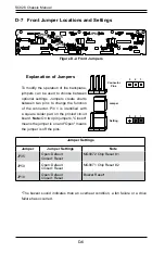
E-8 Front Jumper Locations and Settings
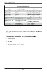
Explanation of Jumpers
To modify the operation of the backplane,
jumpers can be used to choose between
optional settings. Jumpers create shorts
between two pins to change the function
of the connector. Pin 1 is identified with
a square solder pad on the printed circuit
board. Note: On two pin jumpers, "Closed"
means the jumper is on and "Open" means
the jumper is off the pins.
Connector
Pins
Jumper
Setting
3 2 1
3 2 1
PRI_MODE1
ACTLED1
DISABLE
FAN_MONITOR
FANFAIL_LED
_DISABLE
PRI_MODE2
Figure E-2. Front Jumpers
SEC_MODE1
BUZZER_ENB1
SEC_MODE2
Summary of Contents for SC826 Series
Page 12: ...SC826 Chassis Manual 1 6 Notes ...
Page 56: ...SC826 Chassis Manual 4 18 Figure 4 16 Placing the System Fan in the Chassis 3 5 ...
Page 60: ...SC826 Chassis Manual 4 22 Notes ...
Page 72: ...SC826 Chassis Manual A 4 Notes ...
Page 84: ...C 10 SC826 Chassis Manual Notes ...
Page 94: ...D 10 SC826 Chassis Manual Notes ...
Page 134: ...F 18 SC826 Chassis Manual Notes ...
Page 145: ...G 11 Appendix G Cascading Configurations Notes ...

