E-11
Appendix E: CB3 JBOD Control Board
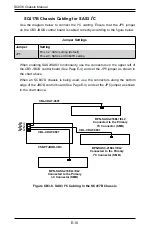
BPN-SAS3-836EL1/EL2
A
Primary
Expander
B
C
D
JP1
A
B
C
D
Secondary
Expander
CBL-CDAT-0601
CSE-PTJBOD-CB3
Connect to the primary I2C
connector (SMB)
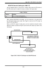
SC836B Chassis Cabling for SAS3 I
2
C
Use the diagram below to connect the I
2
C cabling. Ensure that the JP5 jumper
on the CB3 JBOD control board is cabled correctly according to the figure below.
Figure CB3-9. SAS3 I
2
C Cabling in the SC836B Chassis
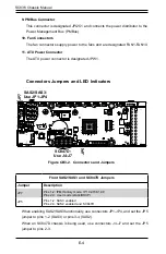
Jumper Settings
Jumper
Setting
JP5
Pins 1-2: SAS3 setting (Default)
Pins 2-3: SAS2 and SC836B setting
When enabling SAS2/SAS3 functionality, use the connectors on the upper left of
the CB3 JBOD control board (See Page E-4) and set the JP5 jumper as shown in
the chart above.
Summary of Contents for SC836 Series
Page 8: ...SC836 Chassis Manual viii Notes ...
Page 12: ...SC836 Chassis Manual 1 4 Notes ...
Page 32: ...2 20 SC836 Chassis Manual Notes ...
Page 38: ...SC836 Chassis Manual 3 6 Notes ...

