3-7
Chapter 3: Configuration and Installation
3-4
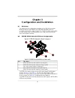
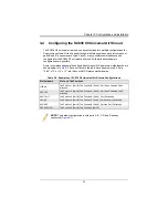
Configuring the SC836 X9 Universal Air Shroud
The SC836 X9 universal air shroud can be customized into multiple configurations for
Supermicro systems. With all parts attached, with three positions each for component
parts B and E, and component part C and D, many possible combinations can be
configured for the SC836 X9 universal air shroud. With parts detached more
configurations are possible.
Some recommended example configurations for specific Supermicro motherboards are
shown below in
. Parts not listed in the table have been removed. All are
13.68” x 13” or 12” x 13” Intel Xeon or AMD Opteron motherboards.
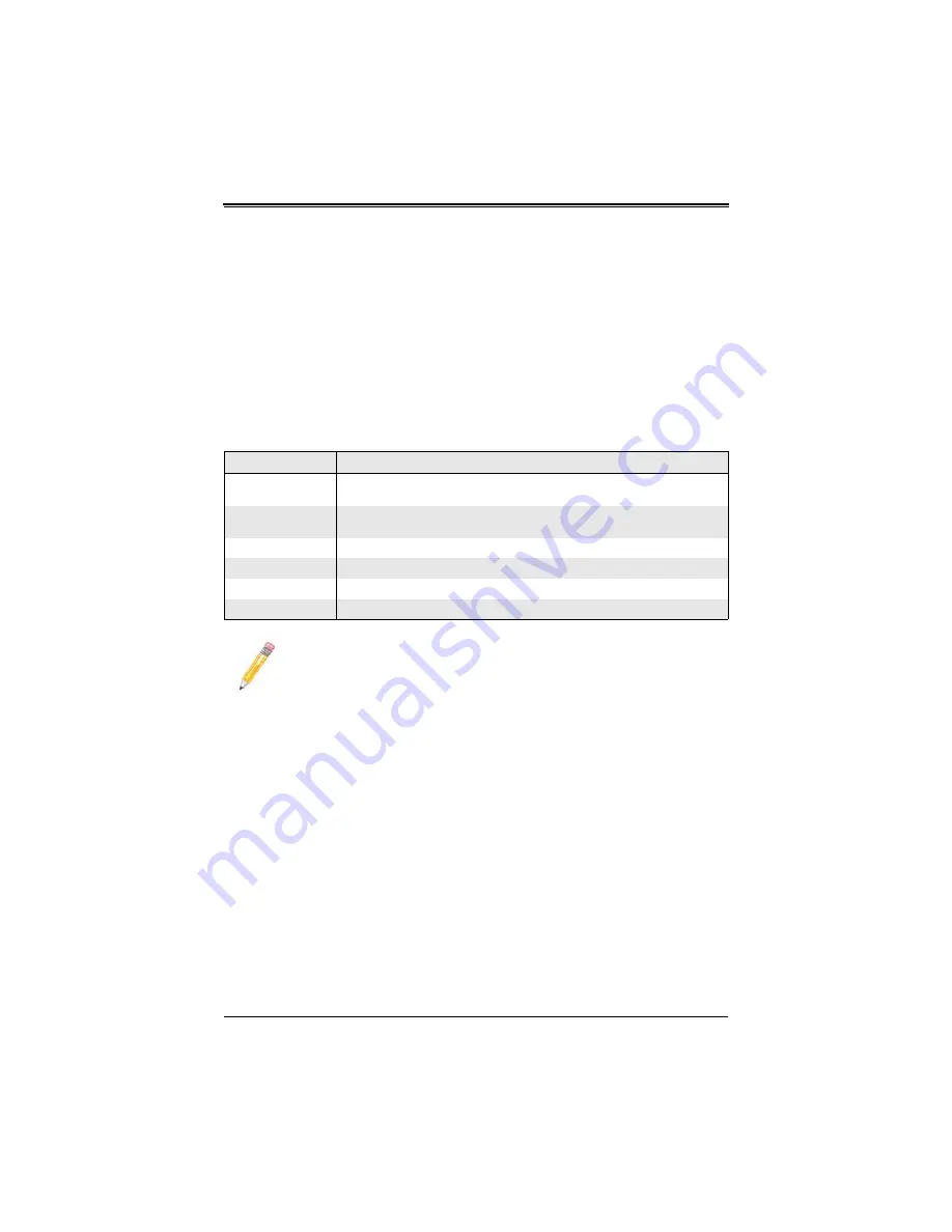
Table 3-2. Examples of SC836 X9 Universal Air Shroud Configurations
Motherboard
Slot and Tab Positions
H8DG6
Tab Position 1 (Part B), Tab Position B (Part E), Part D and Partition Part C
attached
X8DT6-F
Tab Position 0 (Part B), Tab Position A (Part E), Part D and Partition Part C
attached
X8DTN+-F
Tab Position 0 (Part B), Tab Position A (Part E), Part D attached
X9DA6
Tab Position 2 (Part B), Tab Position C (Part E), Partition Part C attached
X9DR6-F
Tab Position 2 (Part B), Tab Position B (Part E), Partition Part C attached
X9DR6-LN4F+
Tab Position 2 (Part B), Tab Position C(Part E)
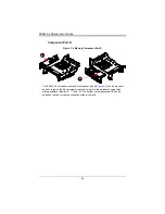
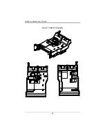
NOTE:
The default configuration is with parts A, B, C, D and E already
connected (
).
Summary of Contents for SC836 X9
Page 1: ...SC836 X9 Universal Air Shroud User s Guide Revison 1 0 ...
Page 4: ...SC836 Air Shroud User s Guide iv Notes ...
Page 6: ...SC836 Air Shroud User s Guide vi Notes ...
Page 10: ...SC836 Air Shroud User s Guide 1 4 Notes ...
Page 20: ...SC836 Air Shroud User s Guide 3 8 Figure 3 7 Default Configuration ...

