D-3
Appendix D: SC836B Added Features
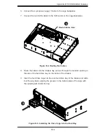
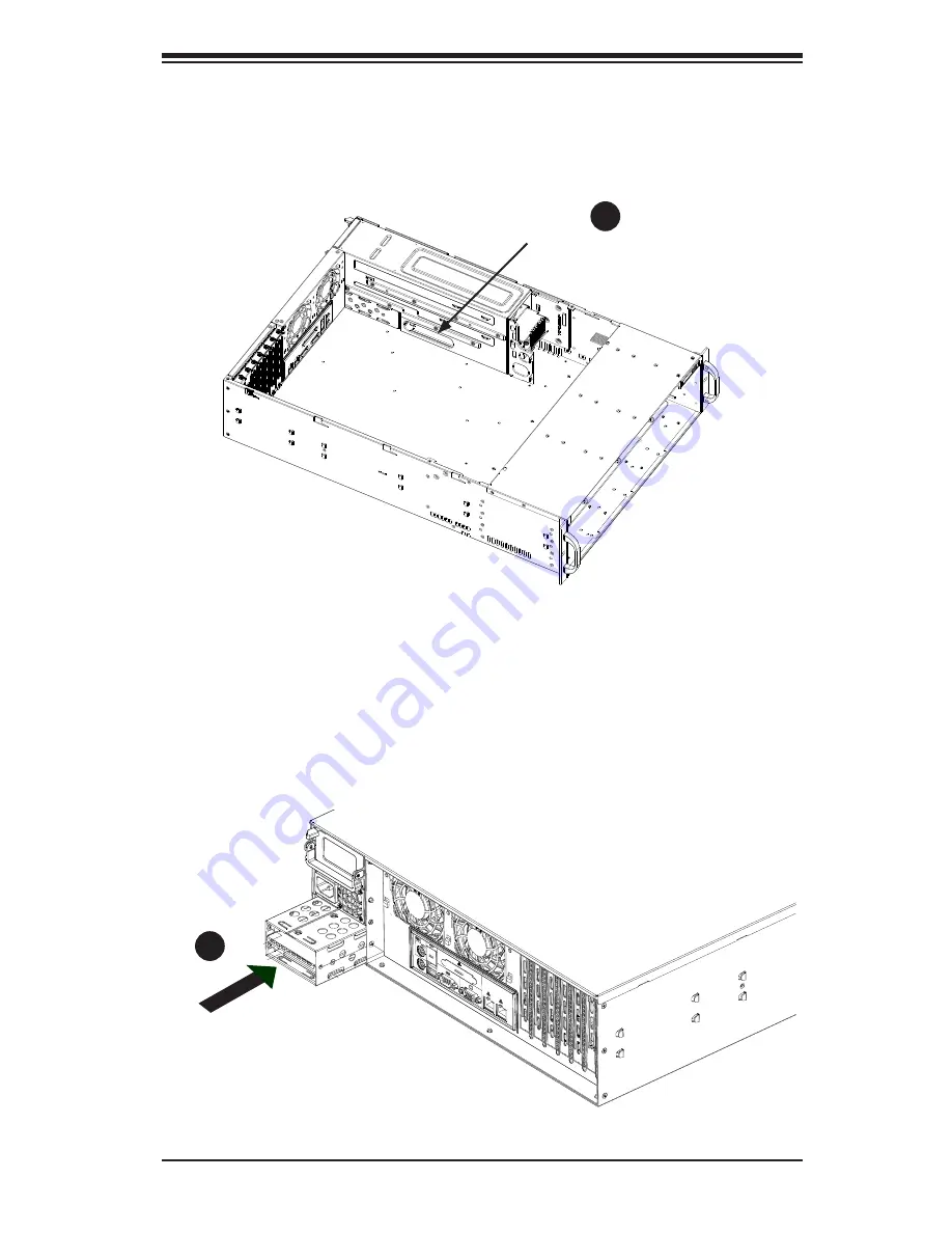
8. Route the cables into the chassis bay and out through the rounded opening in
the side of the hard drive bay on the inside of the chassis.
9. Insert the hard drive cage into the rear hard drive bay of the chassis and slide
it all the way back, aligning the grooves in the bottom plate of the cage with
the upright posts inside the bay.
Figure D-4. Routing the Cables
Figure D-5. Installing the Drive Cage into the Rear Bay
9
1
8
Route Cables Here
6. Connect the 4-pin power supply Y-cable to the cage backplane.
7. Connect the two SATA cables to the SATA ports on the cage backplane.
Summary of Contents for SC836A-R1200B
Page 8: ...SC836 Chassis Manual viii Notes ...
Page 12: ...SC836 Chassis Manual 1 4 Notes ...
Page 32: ...2 20 SC836 Chassis Manual Notes ...
Page 38: ...SC836 Chassis Manual 3 6 Notes ...


