E-3
Appendix E: CB3 JBOD Control Board
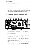
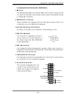
Component and Connector Definitions
1. BMC Chip
The Baseboard Management Controller (BMC) chip monitors the physical state
of a system and provides communication with the system administrator through
an independent connection.
2. SAS2/SAS3 I
2
C Connectors
These connectors are designated JP1-JP4 and allow the power board to be
connected to up to four SAS2/SAS3 backplanes.
3 and 4. Manufacturing Test Connectors
Connectors J3 and FB1 are for Supermicro manufacturing use only.
5. IPMI LAN LED Header
This connector is designated JP6 and is
used to connect to the LED indicators on
the chassis using cable CBL-NTWK-0584
or CBL-NTWK-0587.
6. IPMI LAN Connector
The Intelligent Platform Management Interface (IPMI) LAN connector is
designated J8 and supports connectivity with a local network using cable CBL-
NTWK-0584 or CBL-NTWK-0587.
7. SC847D SAS2 I2C Connectors
The backplane connectors are designated J4-J7 and allow the power board to
be connected to up to four SC847D expanders.
8. Control Panel Connector
This connector is designated JF1 and
connects to the control panel on the
chassis. See Chapter 3 for additional
control panel information.
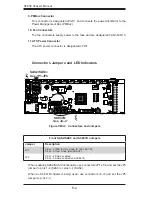
Power Button
Blue+ (OH/Fan Fail/
PWR FaiL/UID LED)
1
NIC1 Link
Reset Button
2
Power Fail LED
HDD LED
FP PWRLED
Reset
PWR
3V3
ID_UID_SW/3/3V Stby
Red+ (Blue LED Cathode)
Ground
Ground
19
20
X
Ground
NMI
X
NIC2 Link
NIC2 Activity
NIC1 Activity
3V3
UID
Ground
Ground
Ground
Link
Act
2 1
Summary of Contents for SC836A-R1200B
Page 8: ...SC836 Chassis Manual viii Notes ...
Page 12: ...SC836 Chassis Manual 1 4 Notes ...
Page 32: ...2 20 SC836 Chassis Manual Notes ...
Page 38: ...SC836 Chassis Manual 3 6 Notes ...

