background image

B-1

Appendix B: Power Supply Specifications 

Appendix B  


SC847BE1C/2C and SC847BA Power Supply 

Specifications

This appendix lists power supply specifications for your chassis system.

SC847BE1C/2C-R1K28LPB, SC847BE1C/2C-R1K28WB, SC847BA

MFR Part #

PWS-1K28P-SQ

AC Input

1000W Output @ 100-140V, 12-8A, 50-60Hz

1280W Output @ 180-240V, 8-6A, 50-60Hz

DC Output

1000W: +12V/83A; +5Vsb/4A

1280W: +12V/106.7A, +5Vsb/4A

Summary of Contents for SC847BA Series

Page 1: ...SC847BE1C R1K28LPB SC847BE2C R1K28LPB SC847BE1C R1K28WB SC847BE2C R1K28WB SC847BA R1K28LPB SC847BE1C 2C and SC847BA CHASSIS SERIES USER S MANUAL 1 0b ...

Page 2: ...turer and customer shall be governed by the laws of Santa Clara County in the State of California USA The State of California County of Santa Clara shall be the exclusive venue for the resolution of any such disputes Super Micro s total liability for all claims will not exceed the price paid for the hardware product California Best Management Practices Regulations for Perchlorate Materials This Pe...

Page 3: ... reconfiguring your chassis into a rack environment This section lists compatible cables power supply specifications and compatible backplanes Not all compatible backplanes are listed Refer to our website for the latest compatible backplane information Appendix A Cables and Hardware This section provides information on cabling and other hardware which is compat ible with your chassis Appendix B Po...

Page 4: ...ge 4 6 4 5 Installing the Motherboard 4 8 Permanent and Optional Standoffs 4 8 4 6 Expansion Card Setup 4 10 Installing Expansion Cards 4 10 4 7 Removing and Installing the Backplanes 4 11 4 8 Air Shroud Modification and Installation 4 15 Air Shroud Installation 4 15 4 9 System Fans 4 18 4 10 Power Supply 4 20 Chapter 5 Rack Installation 5 1 Overview 5 1 5 2 Unpacking the System 5 1 5 3 Preparing ...

Page 5: ...ng fans the SC847BE1C 2C and SC847BA are reliable high quality storage workhorse systems 1 2 Shipping List Please visit the Supermicro website for the latest shiping lists and part numbers for your particular chassis model at www supermicro com Chapter 1 Introduction 1 1 SC847BE1C 2C Chassis Model HDD I O Slots Power Supply SC847BA R1K28LPB 36x 24 front 12 rear 3 5 hot swap HDD bays 7x LP 1280W re...

Page 6: ...adquarters Address Super Micro Computer Inc 980 Rock Ave San Jose CA 95131 U S A Tel 1 408 503 8000 Fax 1 408 503 8008 Email marketing supermicro com General Information support supermicro com Technical Support Website www supermicro com Europe Address Super Micro Computer B V Het Sterrenbeeld 28 5215 ML s Hertogenbosch The Netherlands Tel 31 0 73 6400390 Fax 31 0 73 6416525 Email sales supermicro...

Page 7: ...for all orders that must be mailed when service is complete For faster service RMA authorizations may be requested online http www supermicro com support rma Whenever possible repack the chassis in the original Supermicro carton using the original packaging material If these are no longer available be sure to pack the chassis securely using packaging material to surround the chassis so that it doe...

Page 8: ... or configuring components in the Supermicro chassis These warnings may also be found on our web site at http www supermicro com about policies safety_information cfm Warning This warning symbol means danger You are in a situation that could cause bodily injury Before you work on any equipment be aware of the hazards involved with electrical circuitry and be familiar with standard practices for pr...

Page 9: ...es couramment utilisées pour éviter les accidents Pour prendre connaissance des traductions des avertissements figurant dans les consignes de sécurité traduites qui accompagnent cet appareil référez vous au numéro de l instruction situé à la fin de chaque avertissement CONSERVEZ CES INFORMATIONS 안전을 위한 주의사항 경고 이 경고 기호는 위험이 있음을 알려 줍니다 작업자의 신체에 부상을 야기 할 수 있는 상태에 있게 됩니다 모든 장비에 대한 작업을 수행하기 전에 전기회로와 관련...

Page 10: ...systeem op de voedingsbron aansluit サーキッ ト ブレーカー この製品は 短絡 過電流 保護装置がある建物での設置を前提としています 保護装置の定格が60VDC 20Aを超えないこ とを確認下さい Warnung Dieses Produkt ist darauf angewiesen dass im Gebäude ein Kurzschluss bzw Überstromschutz installiert ist Stellen Sie sicher dass der Nennwert der Schutzvorrichtung nicht mehr als 60VDC 20A beträgt Advertencia Este equipo utiliza el sistema de protección contra cortocircuitos...

Page 11: ...leer of het beveiligde aparaat niet groter gedimensioneerd is dan 60V 20A Advertencia El sistema debe ser disconnected de todas las fuentes de energía y del cable eléctrico quitado de los módulos de fuente de alimentación antes de tener acceso el interior del chasis para instalar o para quitar componentes de sistema Attention Le système doit être débranché de toutes les sources de puissance ainsi ...

Page 12: ...és אזהרה רש בלבד מוסמך צוות את להחליף להתקין אי הציוד עבור שירות לתת או הציוד والمدربيه و لتزكيب استبدال أو خدمة الجهاس هذا يسمح أن يجب فقط المؤهليه للمىظفيه 경고 훈련을 받고 공인된 기술자만이 이 장비의 설치 교체 또는 서비스를 수행할 수 있습니다 Waarschuwing Deze apparatuur mag alleen worden geïnstalleerd vervangen of hersteld door geschoold en gekwalificeerd personeel Warnung Diese Einheit ist zur Installation in Bereichen mit besch...

Page 13: ... ف نتركُبها مناطق محظورة تم انىص َمكن ً إن ىل منطقت محظورة فقط استخذاو خالل من خاصت أداة أو ٌ أ نال أخري وسُهت مألما ومفتاح قفم 경고 이 장치는 접근이 제한된 구역에 설치하도록 되어있습니다 특수도구 잠금 장치 및 키 또는 기타 보안 수단을 통해서만 접근 제한 구역에 들어갈 수 있습니다 Waarschuwing Dit apparaat is bedoeld voor installatie in gebieden met een beperkte toegang Toegang tot dergelijke gebieden kunnen alleen verkregen worden door gebruik te maken van spec...

Page 14: ...ando el sistema está en funcionamiento el voltaje del plano trasero es peligroso Tenga cuidado cuando lo revise Attention Lorsque le système est en fonctionnement des tensions électriques circulent sur le fond de panier Prendre des précautions lors de la maintenance Warning Hazardous voltage or energy is present on the backplane when the system is operating Use caution when servicing Redundant Pow...

Page 15: ...ם החשמל לחוקי תואמת להיות חייבת הציוד المعدات تركيب الكهربائية لل يمتثل أن يجب قىاويه والىطىية المحلية المتعلقة بالكهرباء 경고 시스템이 동작 중일 때 후면판 Backplane 에는 위험한 전압이나 에너지가 발생 합니다 서비스 작업 시 주의하십시오 Waarschuwing Een gevaarlijke spanning of energie is aanwezig op de backplane wanneer het systeem in gebruik is Voorzichtigheid is geboden tijdens het onderhoud האחורי בפנל מתח אז הרה במהלך להיזהר יש המערכת תפ...

Page 16: ...rtencia Los ventiladores podran dar vuelta cuando usted quite ell montaje del ventilador del chasis Mandtenga los dedos los destornilladores y todos los objetos lejos de las aberturas del ventilador Attention Il est possible que les ventilateurs soient toujours en rotation lorsque vous retirerez le bloc ventilateur du châssis Prenez garde à ce que doigts tournevis et autres objets soient éloignés ...

Page 17: ...適合線路 並且可以同時夾住絕緣體和導體 警告 需要使用绞线连接时 请使用经认可的连接端子 如闭环端子或具有接线柱的铲形 端子 这些端子的大小应与线缆相吻合 并且可以将绝缘部分和导体夹紧固定 Attention Quand des fils torsadés sont nécessaires utiliser des douilles terminales homologuées telles que celles à circuit fermé ou du type à plage ouverte avec cosses rebroussées Ces douilles terminales doivent être de la taille qui convient aux fils et doivent être refermées sur la gaine isolante et s...

Page 18: ...い Waarshuwing Wanneer geslagen bedrading vereist is dient u bedrading te gebruiken die voorzien is van goedgekeurde aansluitingspunten zoals het gesloten lus type of het grijperschop type waarbij de aansluitpunten omhoog wijzen Deze aansluitpunten dienen de juiste maat voor de draden te hebben en dienen zowel de isolatie als de geleider vast te klemmen Hazardous voltage or energy may be present on...

Page 19: ...ice Assurez vous que les conducteurs non isolés ne sont pas accessibles lorsque le couvercle est en place دق دهجلا ةرطخلا وأ ةقاطلا نوكت ةدوجوم ىلع تاطحم ةقاطلا ةمصاعلا لادبتسا ءاطغ امئاد امدنع تاطحملا تسيل يف ةمدخلا امم ال كش هيف تالصوملا ريغ لوزعم ال نكمي لوصولا اهيلإ امدنع ءاطغلا يف هناكم Waarshuwing Op DC aansluitingspunten kunnen zich gevaarlijke voltages of energieën voordoen Plaats altijd d...

Page 20: ...u constantly informed of the overall status of the system as well as the activity and health of specific components SC847BE1C 2C and SC847BA models have two buttons on the chassis control panel A reset button and a power on off switch This chapter explains the meanings of all LED indicators and the appropriate responses you may need to take Figure 3 1 Control Panel ...

Page 21: ...a power on off button and a reset button Power Indicates power is being supplied to the system s power supply units This LED should normally be illuminated when the system is operating HDD Indicates IDE channel activity SAS SATA drive and or DVD ROM drive activity when flashing NIC1 Indicates network activity on GLAN1 when flashing NIC2 Indicates network activity on GLAN2 when flashing 1 2 Power F...

Page 22: ... drive carrier indicates a SAS drive A connection to the SAS SATA backplane enables this LED to blink on and off when that particular drive is being accessed When the red LED is blinking it indicates that the system is either building initial izing or rebuilding RAID SCSI Drives This chassis does not support SCSI drives at this time Blue Drive Carrier LED Indicator Status Description Steady on Ind...

Page 23: ...ference while setting up your chassis Review the warnings and precautions listed in the manual before setting up or servicing this chassis These include information in Chapter 2 System Safety and the warnings precautions listed in the setup instructions Safety Warning Before performing any chassis setup or maintenance it is recom mended that the chassis be removed from the rack and placed on a sta...

Page 24: ...w and prevent overheating 1 Removing the Chassis Cover 1 Power down the system and remove the power cords from the rear of the power supplies 2 Remove the screws securing the cover to the chassis 3 Lift the cover up and off the chassis The SC847BE1C 2C and SC847BA chassis have hot swappable 3 5 hard drives which may be removed from the chassis without powering down the system Removing Hard Drive C...

Page 25: ...ives removed from the chassis drive bays Figure 4 4 Removing the Dummy Drive from the Carrier Drive Carrier Dummy Drive 1 1 2 Slide the hard drive into the carrier with the printed circuit board side facing down 3 Carefully align the mounting holes in both the drive carrier and the hard drive 4 Secure the hard drive to the carrier using six screws 5 Replace the drive tray into the chassis Make sur...

Page 26: ...ystem and remove the power cords from the rear of the power supplies Remove the chassis cover as described in section 4 2 2 Place the hard drive cage into the chassis and secure with three screws as illustrated above 3 Replace the chassis cover plug the power cords into the rear of the power supplies and power up the system Removing 2 5 Hard Drives 1 Press the release button on the hard drive carr...

Page 27: ...2 3 As required by your motherboard install standoffs in any areas that do not have a permanent standoff To do this 3a Place a hexagonal standoff screw through the bottom the motherboard tray 3b Secure the screw with the hexagon nut rounded side up Figure 4 11 Chassis Standoffs Figure 4 12 Installing the Motherboard Flat head M4 x 4 mm 0 157 RAIL Round head M4 x 4 mm 0 157 Flat head M5 x 12 mm 0 4...

Page 28: ...ettings see Appendices C D and E of this manual Removing the Front Backplane 1 Power down the system and remove the power cords from the rear of the power supplies Remove the chassis cover as described in Section 4 2 2 Remove the two side screws securing the front backplane to the chassis 3 Remove the four horizontal screws along the top of the front backplane 4 Remove the five horizontal screws t...

Page 29: ...ertical screws securing the backplane to the chassis floor 7 Lift the backplane up and out of the chassis LPB Model Chassis LPB Model Chassis WB Model Chassis WB Model Chassis 1 7 1 7 1 6 1 6 1 5 1 5 1 4 1 4 1 3 Installing the Front Backplane 1 Confirm that the power cords are still disconnected from the power supplies 2 Place the front backplane in the chassis Figure 4 16 Installing the Screws Se...

Page 30: ...erent motherboards Use the chart and illustration below to set up the air shroud for your particular motherboard MCP 310 49004 0N Air Shroud Item Part Number Description MCP 310 49004 0N SC847B SC417B DP X9 universal PC air shroud 1368x13 12x13MB A MCP 310 84707 0N SC847B 417B DP X9 universal PC air shroud main body Remove part A1 when installing the optional rear HDD cage B MCP 310 290041N X9 SC8...

Page 31: ... sary to ensure a proper fit with the motherboard Checking the Airflow Make sure there are no objects to obstruct airflow in and out of the server In addition if you are using a front bezel make sure the bezel s filter is replaced periodically Do not operate the server without drives or drive trays in the drive bays Use only recommended server parts Make sure no wires or foreign objects obstruct a...

Page 32: ...has failed Never run the server for an extended period of time with the chassis cover open 2 Press the fan release tab to lift the failed fan from the chassis and pull it completely out of the chassis 3 Place the new fan into the vacant space in the housing while making sure the arrows on the top of the fan indicating air direction point in the same direc tion as the arrows on the other fans 4 Che...

Page 33: ...be ordered directly from Supermicro see contact information in the Preface Changing the Power Supply 1 If your chassis includes a redundant power supply at least two power mod ules you can leave the server running and remove only one power supply If your server has only one power supply you must power down the server and unplug the power cord 2 Push the release tab on the back of the power supply ...

Page 34: ...SC847BE1C 2C and SC847BA Chassis Manual 4 22 Notes ...

Page 35: ...enerated The system needs to be placed near a grounded power outlet Be sure to read the Rack and Server Precautions in the next section 5 3 Preparing for Setup The box your chassis was shipped in should include two sets of rail assemblies and the mounting screws needed for installing the system into the rack Also included is an optional square hole to round hole converter bracket for use in racks ...

Page 36: ... environment may be greater than the ambient temperature of the room Therefore consideration should be given to installing the equipment in an environment compatible with the manufacturer s maximum rated ambient tempera ture TMRA Reduced Airflow Equipment should be mounted into a rack so that the amount of airflow required for safe operation is not compromised Mechanical Loading Equipment should b...

Page 37: ...s are specifically designed for the left and right side of the chassis Figure 5 1 Identifying the Outer Rail Middle Rail and Inner Rails Left Rail Assembly Shown Inner Rail Rail Assembly Shown with Rails Retracted This Side Faces Outward Locking Tab Middle Rail Outer Rail Figure 5 2 Extending and Releasing the Inner Rail 1 2 1 1 1 3 1 4 Locking Tabs Each inner rail has a locking tab This tab locks...

Page 38: ...ail 3 1 4 1 4 2 Inner Rails Installing the Outer Rails on the Rack Installing the Outer Rails 1 Press upward on the locking tab at the rear end of the middle rail 2 Push the middle rail back into the outer rail 3 Hang the hooks of the front of the outer rail onto the slots on the front of the rack If necessary use screws to secure the outer rails to the rack as illustrated above 4 Pull out the rea...

Page 39: ...7 If necessary for security purposes use screws to secure the chassis handles to the front of the rack Ball Bearing Shuttle Optional Quick Installation Method The following quick installation method may be used to install the chassis onto a rack Installing the Chassis into a Rack 1 Install the whole rail assembly onto the rack as described on page X 7 2 Release the inner rail without retracting th...

Page 40: ...SC847BE1C 2C and SC847BA Chassis Manual 5 10 Notes ...

Page 41: ...es refer to the manufacturer of the motherboard you are using and our Web site at www supermicro com A 2 Cables Included SC847BE1C 2C R1K28LPB SC847BE1C 2C R1K28WB and SC847BA Part Type Qty Length Description CBL 0217L Cable 1 16 pin control panel converter cable for SC826 846 22 cm PBF CBL 0160L Cable 2 6 NEMA5 15P to C13 US power cord 16 AWG PBF default for high Watt CBL 0071L Cable 1 Round 16 p...

Page 42: ...ble Name SAS Cable Quantity 1 Part CBL 0116 Alt Name iPass or Small Four Extending Power Cables Although Supermicro chassis are designed with to be efficient and cost effective some compatible motherboards have power connectors located in different areas To use these motherboards you may have to extend the power cables to the mother boards To do this use the following chart as a guide Power Cable ...

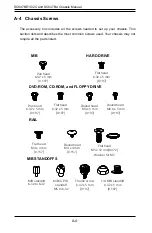
Page 43: ...d Flat head M4 x 4 mm 0 157 RAIL Round head M4 x 4 mm 0 157 Flat head M5 x 12 mm 0 472 Washer for M5 DVD ROM CD ROM and FLOPPY DRIVE Flat head 6 32 x 5 mm 0 197 Pan head 6 32 x 5 mm 0 197 Round head M3 x 5 mm 0 197 Pan head 6 32 x 5 mm 0 197 M B Flat head 6 32 x 5 mm 0 197 HARD DRIVE Thumb screw 6 32 x 5 mm 0 197 M B standoff 6 32 to 6 32 M B STANDOFFS M B CPU standoff M5 to 6 32 Round head M2 6 x...

Page 44: ...pecifications This appendix lists power supply specifications for your chassis system SC847BE1C 2C R1K28LPB SC847BE1C 2C R1K28WB SC847BA MFR Part PWS 1K28P SQ AC Input 1000W Output 100 140V 12 8A 50 60Hz 1280W Output 180 240V 8 6A 50 60Hz DC Output 1000W 12V 83A 5Vsb 4A 1280W 12V 106 7A 5Vsb 4A ...

Page 45: ...SC847BE1C 2C and SC847BA Chassis Manual B 2 Notes ...

Page 46: ...t from ESD Use a grounded wrist strap designed to prevent static discharge Touch a grounded metal object before removing a component from the antistatic bag Handle the backplane by its edges only do not touch its components peripheral chips memory modules or gold contacts When handling chips or modules avoid touching their pins Put the card and peripherals back into their antistatic bags when not ...

Page 47: ... manual reflects BPN SAS3 846EL Revision 1 01 the most current release available at the time of publication Always refer to the Supermicro website at www supermicro com for the latest updates compatible parts and supported configura tions C 5 Overview of the BPN SAS3 846EL1 EL2 Backplanes The BPN SAS3 846EL1 and BPN SAS3 846EL2 model backplanes are identical except that the BPN SAS3 846EL2 backpla...

Page 48: ...H20 MH19 MH18 MH17 MH16 ACTLED HS2 HS1 J30 JP3 J31 JP4 J24 J29 U51 Q873 Q866 Q872 Q871 Q868 Q867 Q870 Q869 U25 U20 U29 U26 U27 U28 U31 U30 U37 U33 U1 EC23 C382 C383 EC9 EC8 EC7 EC6 EC5 EC4 EC3 EC2 EC12 EC11 EC10 EC1 EC24 EC22 EC21 EC20 EC19 EC18 EC17 EC16 EC15 EC14 EC13 J48 J47 L8 L10 L4 L2 L5 L6 PWR1 PWR2 PWR3 PWR4 PWR5 PWR6 R65 TP95 TP94 TP15 TP36 C128 C135 C233 C236 C206 C24 CS21 CT199 12V_LED2...

Page 49: ... the backplane jumpers can be used to choose between optional settings Jumpers create shorts between two pins to change the function of the connector Pin 1 is identified with a square solder pad on the printed circuit board Note On two pin jumpers Closed means the jumper is on and Open means the jumper is off the pins Connector Pins Jumper Setting 3 2 1 3 2 1 LED Testing Only ACTLED JP3 P_MDIO JP4...

Page 50: ...D7 D8 CG4 E1 E2 G2 F2 F1 H2 H1 G1 F7 F8 G8 E7 G7 H7 H8 E8 PRESS FIT CG5 CG2 A1 A2 A7 A8 CG1 B1 B2 B7 B8 C1 C2 C7 C8 D1 D2 D7 D8 CG4 E1 E2 G2 F2 F1 H2 H1 G1 F7 F8 G8 E7 G7 H7 H8 E8 PRESS FIT CG5 CG2 A1 A2 A7 A8 CG1 B1 B2 B7 B8 C1 C2 C7 C8 D1 D2 D7 D8 CG4 E1 E2 G2 F2 F1 H2 H1 G1 F7 F8 G8 E7 G7 H7 H8 E8 PRESS FIT CG5 CG2 A1 A2 A7 A8 CG1 B1 B2 B7 B8 C1 C2 C7 C8 D1 D2 D7 D8 CG4 E1 E2 G2 F2 F1 H2 H1 G1 ...

Page 51: ... 4 ACT4 FAIL4 SAS 5 ACT5 FAIL5 SAS 6 ACT6 FAIL6 SAS 7 ACT7 FAIL7 SAS 8 ACT8 FAIL8 SAS 9 ACT 9 FAIL9 SAS 10 ACT10 FAIL10 SAS 11 ACT11 FAIL11 SAS 12 ACT12 FAIL12 SAS 13 ACT13 FAIL13 SAS 14 ACT14 FAIL14 SAS 15 ACT15 FAIL15 SAS 16 ACT16 FAIL16 SAS 17 ACT17 FAIL17 SAS 18 ACT18 FAIL18 SAS 19 ACT19 FAIL19 SAS 20 ACT20 FAIL20 SAS 21 ACT21 FAIL21 SAS 22 ACT22 FAIL22 SAS 23 ACT23 FAIL23 ...

Page 52: ... D8 CG4 E1 E2 G2 F2 F1 H2 H1 G1 F7 F8 G8 E7 G7 H7 H8 E8 PRESS FIT CG5 CG2 A1 A2 A7 A8 CG1 B1 B2 B7 B8 C1 C2 C7 C8 D1 D2 D7 D8 CG4 E1 E2 G2 F2 F1 H2 H1 G1 F7 F8 G8 E7 G7 H7 H8 E8 PRESS FIT CG5 CG2 BPN SAS3 846EL2 REV 1 01 DESIGNED IN USA 1 1 4 1 4 1 4 1 4 1 4 1 4 14 6 7 8 13 2 6 7 8 9 13 11 12 22 11 12 22 11 11 12 22 11 12 22 11 12 22 12 13 14 23 2 11 12 13 14 23 7 12 13 18 19 24 6 7 12 13 18 19 24...

Page 53: ...1 11 12 22 11 12 22 11 12 22 12 13 14 23 2 11 12 13 14 23 7 12 13 18 19 24 6 7 12 13 18 19 24 1 5 10 15 20 25 30 AK AE Y R K E A 1 5 10 15 20 25 30 AK AE Y R K E A 3 2 1 4 3 2 1 4 1 4 1 4 1 4 1 4 1 4 1 4 A C A C A C A C A C BAR CODE WWN WWN U21 U4 U19 U3 L9 L7 F73 BC57 BC29 C165 C107 BC10 BC96 L3 C308 C177 C122 C354 C76 U35 J52 J51 J49 J50 MH15 MH13 MH14 MH27 MH26 MH25 MH24 MH23 MH22 MH21 MH20 MH1...

Page 54: ...G1 F7 F8 G8 E7 G7 H7 H8 E8 PRESS FIT CG5 CG2 BPN SAS3 846EL2 REV 1 01 DESIGNED IN USA 1 1 4 1 4 1 4 1 4 1 4 1 4 14 6 7 8 13 2 6 7 8 9 13 11 12 22 11 12 22 11 11 12 22 11 12 22 11 12 22 12 13 14 23 2 11 12 13 14 23 7 12 13 18 19 24 6 7 12 13 18 19 24 1 5 10 15 20 25 30 AK AE Y R K E A 1 5 10 15 20 25 30 AK AE Y R K E A 3 2 1 4 3 2 1 4 1 4 1 4 1 4 1 4 1 4 1 4 A C A C A C A C A C BAR CODE WWN WWN U21...

Page 55: ...pter Figure C 14 Dual External Host Bus Adapter Single External Host Bus Adapter IMPORTANT See Section C 13 of this manual Failover with RAID Cards and Multiple HBAs for important information on supported configurations CBL SAST 0531 Internal Cable CBL SAST 0573 External Cable Mini SAS HD Internal to External Adapter AOM SAS3 16I16E LP HBA Port B Expander 2 Power Card Port B Expander 2 Port A Expa...

Page 56: ...en servers and JBODs Single HBA Configuration Cables Figure C 16 External Mini SAS HD to External Mini SAS HD Cable Figure C 17 Mini SAS HD Internal to External Adapter CBL SAST 0573 External Cable Port A Expander 1 HBA HBA Port A Expander 1 Port B Expander 2 CBL SAST 0531 Internal Cable Connecting Multiple Backplanes in a Dual Channel Environment This section describes the cables used when cascad...

Page 57: ...C 18 SC847BE1C 2C and SC847BA Chassis Manual Notes ...

Page 58: ...rom ESD Use a grounded wrist strap designed to prevent static discharge Touch a grounded metal object before removing a component from the antistatic bag Handle the backplane by its edges only do not touch its components peripheral chips memory modules or gold contacts When handling chips or modules avoid touching their pins Put the card and peripherals back into their antistatic bags when not in ...

Page 59: ...anual reflects BPN SAS3 826EL Revision 1 00 the most current release available at the time of publication Always refer to the Supermicro Web site at www supermicro com for the latest updates compatible parts and supported con figurations D 5 Overview of the BPN SAS3 826EL1 EL2 Backplanes The BPN SAS3 826EL1 and BPN SAS3 826EL2 model backplanes are identical except that the BPN SAS3 826EL2 backplan...

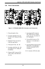
Page 60: ...U22 J23 J22 J18 J19 JPW2 JPW1 JPW3 U34 U17 U14 U21 U16 U20 U6 C52 J16 J17 MH7 MH6 MH9 MH8 MH5 MH1 MH2 MH3 MH4 U30 U24 U7 U27 JP1 R97 C511 C5 J J I2C 4 SEC UART PRI UART 12V 5V HB LED HB LED PRI SDB PRI J4 PRI J3 PRI J2 PRI J1 I2C 0 TEST ACT LED SEC J4 SEC J3 SEC J2 SEC J1 SEC SDB SECONDARY EXPANDER PRIMARY EXPANDER D 6 Front Connectors 1 Primary expander chip 2 Secondary expander chip not present ...

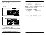
Page 61: ... function of the connector Pin 1 is identified with a square solder pad on the printed circuit board Note On two pin jumpers Closed means the jumper is on and Open means the jumper is off the pins Connector Pins Jumper Setting 3 2 1 3 2 1 ACT LED TEST D 7 Front Connector and Pin Definitions Backplane Main Power 4 Pin Connector Pin Definition 1 12V 2 and 3 Ground 4 5V 3 Backplane Main Power Connect...

Page 62: ...G1 B1 B2 B7 B8 C1 C2 C7 C8 D1 D2 D7 D8 CG4 E8 E7 E1 E2 G2 F2 F1 H2 H1 G1 G8 F8 F7 H8 H7 G7 CG3 CG5 CG2 A C A C A C A C A C A C A C A C A C A C A C A C A C A C A C A C A A C A C A C A C A C 3 2 1 4 3 2 1 4 4 1 4 1 4 1 4 1 4 4 1 4 1 A7 A8 A1 A2 CG1 CG2 B1 B2 B7 B8 C1 C2 C7 C8 D1 D2 D7 D8 CG3 E8 E7 E1 E2 G2 F2 F1 H2 H1 G1 G8 F8 F7 H8 H7 G7 A7 A8 A1 A2 CG1 CG2 B1 B2 B7 B8 C1 C2 C7 C8 D1 D2 D7 D8 CG3 E...

Page 63: ... E 5 H 5 1 A E H A 1 E 5 H 5 1 A E H A1 A2 A7 A8 CG1 CG2 B1 B2 B7 B8 C1 C2 C7 C8 D1 D2 D7 D8 CG3 E1 E2 G2 F2 F1 H2 H1 G1 F7 F8 G8 E7 G7 H7 H8 E8 PRESS FIT A1 A2 A7 A8 CG1 CG2 B1 B2 B7 B8 C1 C2 C7 C8 D1 D2 D7 D8 CG3 E1 E2 G2 F2 F1 H2 H1 G1 F7 F8 G8 E7 G7 H7 H8 E8 PRESS FIT 1 5 10 15 20 25 26 Y R K E A 1 5 10 15 20 25 26 AF AE Y R K E A 1 2 3 1 2 3 1 DESIGNED IN USA BAR CODE 6 7 12 13 24 L22 J14 J15...

Page 64: ...SAS HBA SAS HBA Port A Expander 1 Port A Expander 1 Port B Expander 2 Port B Expander 2 Figure D 7 Single HBA SAS HBA SAS HBA SAS HBA SAS HBA Port A Expander 1 Port B Expander 2 IMPORTANT For RAID controllers redundancy is achieved through port failover For multiple HBAs MPIO software is required to achieve failover protection D 13 Failover with RAID Cards and Multiple HBAs The BPN SAS3 826EL back...

Page 65: ... ACT LED SEC J4 SEC J3 SEC J2 SEC J1 SEC SDB SECONDARY EXPANDER PRIMARY EXPANDER BPN SAS3 826EL1 REV 1 00 SAS CODE SAS CODE A1 A2 A7 A8 CG1 B1 B2 B7 B8 C1 C2 C7 C8 D1 D2 D7 D8 CG4 E1 E2 G2 F2 F1 H2 H1 G1 F7 F8 G8 E7 G7 H7 H8 E8 PRESS FIT CG5 CG2 A1 A2 A7 A8 CG1 B1 B2 B7 B8 C1 C2 C7 C8 D1 D2 D7 D8 CG4 E1 E2 G2 F2 F1 H2 H1 G1 F7 F8 G8 E7 G7 H7 H8 E8 PRESS FIT CG5 CG2 A C A C A C A C A C 3 2 1 4 3 2 ...

Page 66: ... C5 J J I2C 4 SEC UART PRI UART 12V 5V HB LED HB LED PRI SDB PRI J4 PRI J3 PRI J2 PRI J1 I2C 0 TEST ACT LED SEC J4 SEC J3 SEC J2 SEC J1 SEC SDB SECONDARY EXPANDER PRIMARY EXPANDER PRI J1 PRI J2 PRI J3 PRI J4 PRI J1 PRI J2 PRI J3 PRI J4 SED J1 SED J2 SED J3 SED J4 CBL SAST 0531 Internal Cable CBL SAST 0573 External Cable Mini SAS HD Internal to External Adapter ACM SAS3 16I16E ADP HBA Port B Expand...

Page 67: ...1 A2 A7 A8 CG1 CG2 B1 B2 B7 B8 C1 C2 C7 C8 D1 D2 D7 D8 CG3 E1 E2 G2 F2 F1 H2 H1 G1 F7 F8 G8 E7 G7 H7 H8 E8 PRESS FIT 1 5 10 15 20 25 26 Y R K E A 1 5 10 15 20 25 26 AF AE Y R K E A 1 2 3 1 2 3 1 DESIGNED IN USA BAR CODE 6 7 12 13 24 L22 J14 J15 LED29 LED28 LED27 LED26 LED25 L3 L23 C496 C502 C501 C500 C499 C498 C497 C495 C494 C492 C491 C689 C681 J21 J20 U22 J23 J22 J18 J19 JPW2 JPW1 JPW3 U34 U17 U1...

Page 68: ...D 18 SC847BE1C 2C and SC847BA Chassis Manual Notes ...

Page 69: ...SD Use a grounded wrist strap designed to prevent static discharge Touch a grounded metal object before removing a component from the antistatic bag Handle the backplane by its edges only do not touch its components peripheral chips memory modules or gold contacts When handling chips or modules avoid touching their pins Put the card and peripherals back into their antistatic bags when not in use E...

Page 70: ...AS3 846EL1 The BPN SAS3 846EL2 is divided into a two sections with the primary components on the right side of the board and the secondary components on the left SAS3 backplanes are not compatible with legacy SAS 3 Gbps SATA 1 5 Gbps backplanes or lower E 5 The BPN SAS3 826EL Rear Backplane The BPN SAS3 826EL backplane has been designed to utilize the most up to date technology available providing...

Page 71: ..._MDIO S_SDB S_UART EXP I2C0 EXP I2C4 5V GND 12V 5V GND 12V 5V GND 12V 5V GND 12V J50 J49 J52 J51 SEC PRI CBL SAST 0573 External Cable Power Card Port A Expander 1 Port B Expander 2 Connecting the Front and Rear Backplanes This section describes the cables used when cascading from the front backplane to the rear backplane from multiple HBAs These connections use CBL SAST 0531 internal cables and CB...

Page 72: ...E 4 SC847BE1C 2C and SC847BA Chassis Manual Notes ...

Page 73: ...ic discharge Touch a grounded metal object before removing a component from the antistatic bag Handle the backplane by its edges only do not touch its components peripheral chips memory modules or gold contacts When handling chips or modules avoid touching their pins Put the card and peripherals back into their antistatic bags when not in use F 2 General Safety Guidelines Always disconnect power c...

Page 74: ...aphics shown in this manual F 4 Introduction to the BPN SAS 846A Backplane The BPN SAS 826A backplane has been designed to utilize the most up to date technology available providing your system with reliable high quality performance This manual reflects BPN SAS 826A Revision 1 00 the most current release avail able at the time of publication Always refer to the Supermicro Web site at www su permic...

Page 75: ...52 U24 U41 JP69 JP78 RP1 U2 JP26 JP47 U18 BAR CODE B B SAS IN 1 SAS IN 2 9072 RST 9071 RST ACT4 ACT11 ACT10 ACT9 ACT8 ACT3 ACT2 ACT1 ACT7 ACT6 ACT5 ACT0 2 3 I2C 1 2 SGPIO JP84 MODE C 2 3 55 1 2 50 C C OPEN 45 JP45 OH 2 TEMP C C C 2 3 55 1 2 50 OPEN 45 JP25 OH 1 TEMP ALARM 1 ALARM 2 ACT_IN 8 11 ACT_IN 0 7 UPGRADE 2 UPGRADE 1 SAS IN 3 I2C 3 I2C 2 I2C 1 BUZZER RESET REV 1 00 SAS826A Front Connectors ...

Page 76: ...headers are located on the front panel For the activity lead headers to work properly connect to them using a 10 pin LED cable This is only used when the activity LED is not supported by the hard drive SAS Activity LED Header Pin Definitions Pin Definition Pin Definition 1 ACT IN 8 6 ACT IN 12 2 ACT IN 9 7 ACT IN 13 3 ACT IN 10 8 ACT IN 14 4 ACT IN 11 9 ACT IN 15 5 Ground 10 Empty 3 4 5 I2 C Conne...

Page 77: ...4 U41 JP69 JP78 RP1 U2 JP26 JP47 U18 BAR CODE B B SAS IN 1 SAS IN 2 9072 RST 9071 RST ACT4 ACT11 ACT10 ACT9 ACT8 ACT3 ACT2 ACT1 ACT7 ACT6 ACT5 ACT0 2 3 I2C 1 2 SGPIO JP84 MODE C 2 3 55 1 2 50 C C OPEN 45 JP45 OH 2 TEMP C C C 2 3 55 1 2 50 OPEN 45 JP25 OH 1 TEMP ALARM 1 ALARM 2 ACT_IN 8 11 ACT_IN 0 7 UPGRADE 2 UPGRADE 1 SAS IN 3 I2C 3 I2C 2 I2C 1 BUZZER RESET REV 1 00 SAS826A JP18 JP35 JP84 JP50 F ...

Page 78: ...3 Q32 REV 1 00 SAS826A FAIL 11 ACT 11 FAIL 10 ACT 10 FAIL 9 ACT 9 FAIL 8 ACT 8 FAIL 6 ACT 6 ACT 7 FAIL 7 ACT 5 FAIL 5 ACT 4 FAIL 4 8 9 10 11 7 6 5 4 3 2 1 0 SAS SAS SAS SAS SAS SAS SAS SAS SAS SAS SAS SAS FAIL 3 ACT 3 ACT 2 FAIL 2 ACT 1 FAIL 1 ACT 0 FAIL 0 F 7 Rear Connectors and LED Indicators Rear SAS SATA Connectors Rear Connector SAS Drive Number Rear Connector SAS Drive Number SAS 0 SAS SATA ...

Page 79: ...F 10 SC847BE1C 2C and SC847BA Chassis Manual Notes ...

Page 80: ...ned to prevent static discharge Touch a grounded metal object before removing a component from the antistatic bag Handle the RAID card by its edges only do not touch its components peripheral chips memory modules or gold contacts When handling chips or modules avoid touching their pins Put the card and peripherals back into their antistatic bags when not in use G 2 General Safety Guidelines Always...

Page 81: ... shown in this manual G 4 Introduction to the BPN SAS 846A Backplane The BPN SAS 846A backplane has been designed to utilize the most up to date technology available providing your system with reliable high quality performance This manual reflects BPN SAS 846A Revision 1 00 the most current release avail able at the time of publication Always refer to the Supermicro Web site at www su permicro com...

Page 82: ...T 2 3 NO RESET 1 2 RESET 2 3 NO RESET 1 2 RESET 22 23 20 21 18 19 16 17 14 15 12 13 10 11 8 9 6 7 4 5 3 2 1 0 JP129 9072 3 RESET JP35 9072 1 RESET JP50 9072 2 RESET BUZZER RESET 2 3 NO FAN 1 2 WITH FAN JP61 FAN 1 SELECT JP64 FAN 4 SELECT JP63 FAN 3 SELECT JP62 FAN 2 SELECT 2 3 NO FAN 1 2 WITH FAN JP97 FAN 1 SELECT JP98 FAN 2 SELECT JP99 FAN 3 SELECT JP100 FAN 4 SELECT C C C OPEN 45 1 2 50 2 3 55 J...

Page 83: ...14 R415 R148 R112 R147 R344 R104 R113 R305 R367 R167 R184 R127 R183 R128 R185 R168 R270 R494 R575 R591 R619 R623 R624 R629 R220 R219 R218 R217 R425 R424 R423 R405 R404 R403 Y3 Y2 Y1 JSM1 JSM2 JSM3 JSM4 JSM5 JSM6 F14 F19 F20 F5 F6 4 1 JP60 4 1 JP58 4 1 4 1 JP54 MH15 MH14 MH13 MH12 MH11 U63 JP108 JP47 JP26 U2 JP115 JP78 JP69 U91 U24 JP116 JP117 JP52 JP96 JP95 JP37 JP10 JP13 JP46 JP48 5V 12V GND GND ...

Page 84: ...5 JSM6 F14 F19 F20 F5 F6 4 1 JP60 4 1 JP58 4 1 4 1 JP54 MH15 MH14 MH13 MH12 MH11 U63 JP108 JP47 JP26 U2 JP115 JP78 JP69 U91 U24 JP116 JP117 JP52 JP96 JP95 JP37 JP10 JP13 JP46 JP48 5V 12V GND GND JP109 5V 12V GND GND JP110 JP105 JP106 D64 D113 D116 JP64 1 3 JP63 1 3 JP62 1 3 JP61 JP50 1 3 JP35 1 JP129 1 3 JP107 1 3 JP97 JP98 JP99 JP45 JP25 JP100 JP18 F4 D54 A C D53 A C D36 A C D3 A C D51 A C D49 A ...

Page 85: ...1 SAS 12 SAS SATA HDD 13 SAS 1 SAS SATA HDD 2 SAS 13 SAS SATA HDD 14 SAS 2 SAS SATA HDD 3 SAS 14 SAS SATA HDD 15 SAS 3 SAS SATA HDD 4 SAS 15 SAS SATA HDD 16 SAS 4 SAS SATA HDD 5 SAS 16 SAS SATA HDD 17 SAS 5 SAS SATA HDD 6 SAS 17 SAS SATA HDD 18 SAS 6 SAS SATA HDD 7 SAS 18 SAS SATA HDD 19 SAS 7 SAS SATA HDD 8 SAS 19 SAS SATA HDD 20 SAS 8 SAS SATA HDD 9 SAS 20 SAS SATA HDD 21 SAS 9 SAS SATA HDD 10 S...

Page 86: ...er form be reasonably expected to result in significant injury or loss of life or catastrophic property damage Accordingly Supermicro disclaims any and all liability and should buyer use or sell such products for use in such ultra hazardous applications it does so entirely at its own risk Furthermore buyer agrees to fully indemnify defend and hold Supermicro harmless for and against any and all cl...

Reviews: