D-5
Appendix D: BPN-SAS3-826EL Backplane Specifications
D-4
SC847BE1C/2C and SC847BA Chassis Manual
BPN-SAS3-826EL1
REV:1.00
SAS CODE
SAS CODE
A1
A2
A7
A8
CG
1
B1
B2
B7
B8
C1
C2
C7
C8
D1
D2
D7
D8
CG
4
E1
E2
G2
F2
F1
H2
H1
G1
F7
F8
G8
E7
G7
H7
H8
E8
PRESS FIT
CG
5
CG
2
A1
A2
A7
A8
CG
1
B1
B2
B7
B8
C1
C2
C7
C8
D1
D2
D7
D8
CG
4
E1
E2
G2
F2
F1
H2
H1
G1
F7
F8
G8
E7
G7
H7
H8
E8
PRESS FIT
CG
5
CG
2
A
C
A
C
A
C
A
C
A
C
+
+
+
+
+
+
+
+
+
+
+
+
+
+
+
+
3
2
1
4
3
2
1
4
1
4
1
4
1
4
1
4
1
4
1
4
1
4
11
12
22
A
1
E
5
H
5
1
A
E
H
A
1
E
5
H
5
1
A
E
H
A1
A2
A7
A8
CG
1
CG
2
B1
B2
B7
B8
C1
C2
C7
C8
D1
D2
D7
D8
CG
3
E1
E2
G2
F2
F1
H2
H1
G1
F7
F8
G8
E7
G7
H7
H8
E8
PRESS FIT
A1
A2
A7
A8
CG
1
CG
2
B1
B2
B7
B8
C1
C2
C7
C8
D1
D2
D7
D8
CG
3
E1
E2
G2
F2
F1
H2
H1
G1
F7
F8
G8
E7
G7
H7
H8
E8
PRESS FIT
1
5
10
15
20
25
26
Y
R
K
E
A
1
5
10
15
20
25
26
AF
AE
Y
R
K
E
A
1
2
3
1
2
3
1
DESIGNED IN USA
BAR CODE
6
7
12
13
24
L22
J14
J15
LED29
LED28
LED27
LED26
LED25
L3
L23
C496
C502
C501
C500
C499
C498
C497
C495
C494
C492
C491
C689
C681
J21
J20
U22
J23
J22
J18
J19
JPW2
JPW1
JPW3
U34
U17
U14
U21
U16
U20
U6
C52
J16
J17
MH7
MH6
MH9
MH8
MH5
MH1
MH2
MH3
MH4
U30
U24
U7
U27
JP1
R97
C511
C5
J*
J*
I2C#4
SEC-UART
PRI-UART
12V 5V
HB-LED
HB
-LED
PRI-SDB
PRI-
J4
PRI-
J3
PRI-
J2
PRI-
J1
I2C#0
TEST
ACT-LED
SEC-
J4
SEC-
J3
SEC-
J2
SEC-
J1
SEC-SDB
SECONDARY EXPANDER
PRIMARY EXPANDER
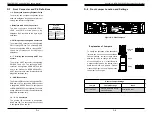
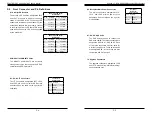
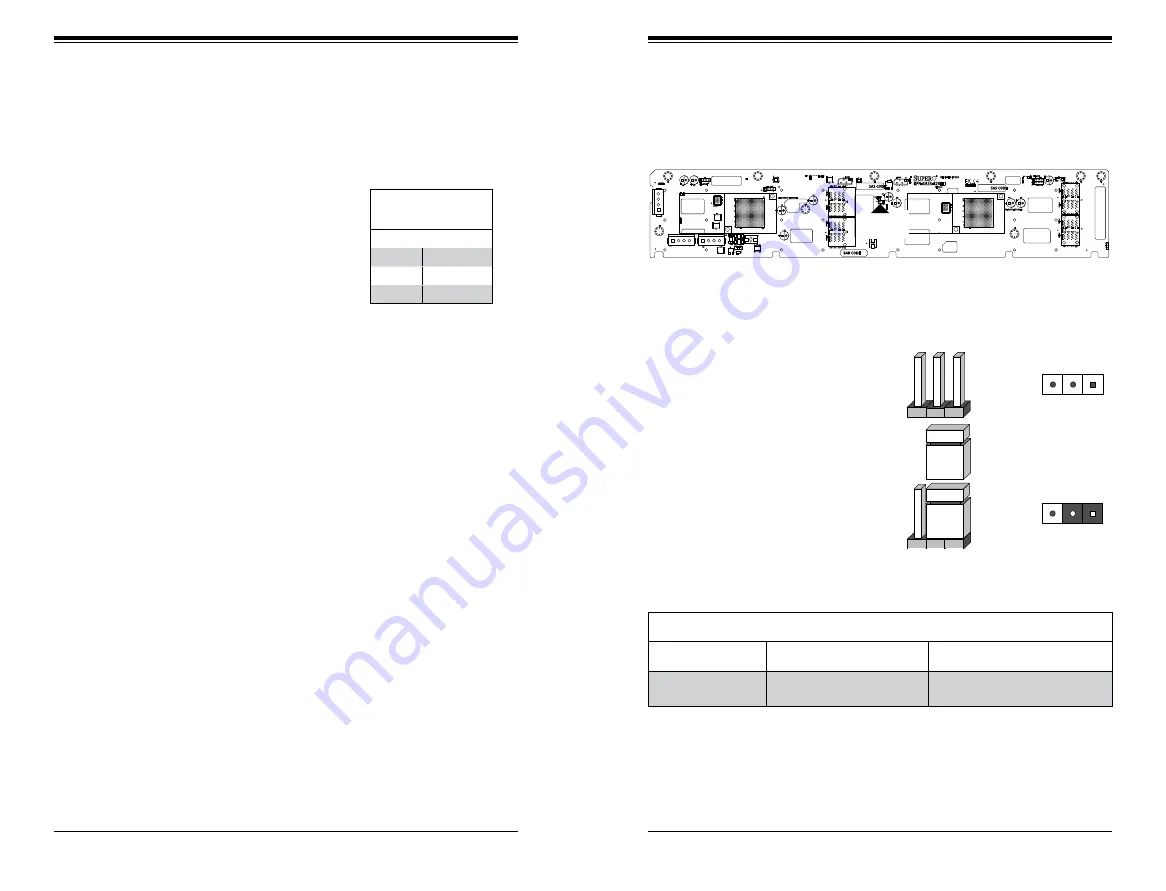
D-8 Front Jumper Location and Settings
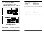
Explanation of Jumpers
To modify the operation of the backplane,
jumpers can be used to choose between
optional settings. Jumpers create shorts
between two pins to change the function
of the connector. Pin 1 is identified with
a square solder pad on the printed circuit
board. Note: On two pin jumpers, "Closed"
means the jumper is on and "Open" means
the jumper is off the pins.
Connector
Pins
Jumper
Setting
3 2 1
3 2 1
ACT-LED
TEST
D-7 Front Connector and Pin Definitions
Backplane
Main Power
4-Pin Connector
Pin# Definition
1
+12V
2 and 3
Ground
4
+5V
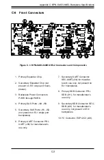
3. Backplane Main Power Connectors
The 4-pin connectors, designated JPW1,
JPW2, and JPW3, provide power to the
backplane. See the table on the right for pin
definitions.
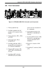
1. - 2. Primary and Secondary Expander Chips
The primary and secondary expander chips
allow the backplane to support dual port, cas-
cading, and failover configurations.
4. - 5. Primary and Secondary SAS Connectors
The primary SAS connectors are designated
PRI-J1 through PRI-J4. The secondary SAS
Ports are designated SED-J1 through SED-
J4 and are not present on EL1 single port
backplanes.
6. - 7. Primary and Secondary UART Con-
nectors
The primary UART connector is designated
PRI-UART and J22. The secondary UART
connector is designated SED-UART and J23
and is not present on BPN-SAS3-826EL1.
UART connectors are used for manufacturer's
diagnostic purposes only.
8. - 9. SDB Connectors
The Primary SDB connector is designated PRI-
SDB and J18. The secondary SDB connector
is designated SED-SDB and J19. (Not present
on BPN-SAS3-826EL1 backplanes) These are
debug connectors used for the manufacturer's
diagnostic purposes only.
10. - 11. I
2
C Connectors
The primary I2C connector. is designated
I2C#0 and J20. The secondary I2C connector
is designated I2C#4 and J21.
Figure D-2. Front Jumpers
General Jumper Settings
Jumper
Jumper Settings
Note
ACT-LED TEST
Open: Disabled (Default)
Closed: Enabled
Activity LED test.
Summary of Contents for SC847BA Series
Page 34: ...SC847BE1C 2C and SC847BA Chassis Manual 4 22 Notes ...
Page 40: ...SC847BE1C 2C and SC847BA Chassis Manual 5 10 Notes ...
Page 45: ...SC847BE1C 2C and SC847BA Chassis Manual B 2 Notes ...
Page 57: ...C 18 SC847BE1C 2C and SC847BA Chassis Manual Notes ...
Page 68: ...D 18 SC847BE1C 2C and SC847BA Chassis Manual Notes ...
Page 72: ...E 4 SC847BE1C 2C and SC847BA Chassis Manual Notes ...
Page 79: ...F 10 SC847BE1C 2C and SC847BA Chassis Manual Notes ...

