
SC848 Chassis Manual
3-2
3-3 Control Panel LEDs
The control panel located on the left handle of the SC848 chassis has five LEDs.
These LEDs provide you with critical information related to different parts of the
system. This section explains what each LED indicates when illuminated and any
corrective action you may need to take.
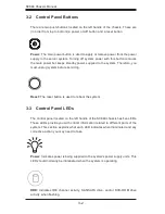
Power:
The main power button is used to apply or remove power from the power
supply to the server system. Turning off system power with this button removes
the main power but keeps standby power supplied to the system. Therefore, you
must unplug system before servicing.
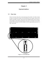
3-2 Control Panel Buttons
There are two push-buttons located on the left handle of the chassis. These are
(in order from top to bottom) a power on/off button and a reset button.
Power:
Indicates power is being supplied to the system's power supply units. This
LED should normally be illuminated when the system is operating.
HDD:
Indicates IDE channel activity. SAS/SATA drive, and/or DVD-ROM drive
activity when flashing.
Reset:
The reset button is used to reboot the system.
Summary of Contents for SC848A-R1800B
Page 1: ...SC848 CHASSIS SERIES USER S MANUAL 1 0a SUPER SC848A R1800B ...
Page 8: ...SC848 Chassis Manual viii Notes ...
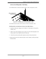
Page 35: ...4 15 Chapter 4 Chassis Setup and Maintenance Figure 4 18 Installing a Front System Fan ...
Page 52: ...SC848 Chassis Manual 4 32 Notes ...
Page 62: ...SC848 Chassis Manual 5 10 Notes ...