4-7
Chapter 4: Chassis Setup and Maintenance
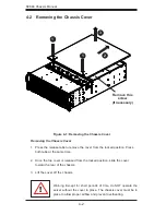
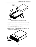
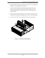
Remove
Screws
Remove
Screws
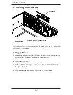
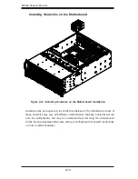
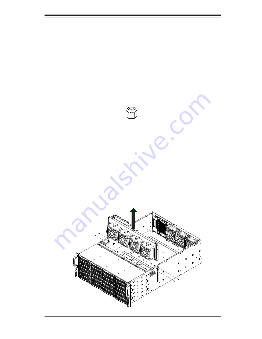
Installing the Motherboard
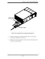
Review the documentation that came with your motherboard. Become familiar
1.
with component placement, requirements, precautions, and cable connec-
tions.
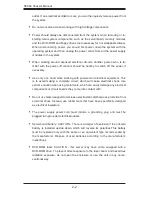
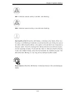
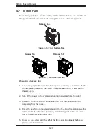
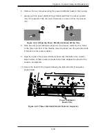
Remove the four screws which mount the middle bracket onto the chassis as
2.
illustrated below. (Unplug the fan connectors from the original motherboard if
necessary) and lift the middle bracket up and out of the chassis.
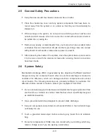
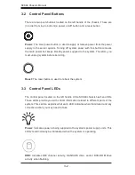
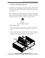
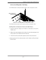
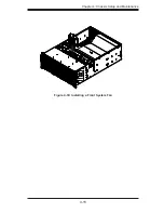
Figure 4-8: Chassis Standoffs
Figure 4-9: Removing the Middle Bracket
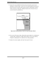
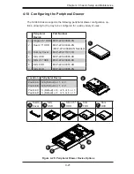
Permanent and Optional Standoffs
Standoffs prevent short circuits by securing space between the motherboard and
the chassis surface. The SC848 chassis includes permanent standoffs in locations
used by most motherboards. These standoffs are included in the SC848 acces-
sories packaging.
Some motherboards require additional screws for heatsinks, general components
and/or non-standard security. Optional standoffs are included to these mother-
boards. To use an optional standoff, you must place the standoff through the bottom
the chassis and secure it with a wrench, with the rounded end upward.
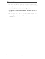
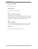
Flat head
M4 x 4 mm
[0.157]
RAIL
Round head
M4 x 4 mm
[0.157]
Flat head
M5 x 12 mm[0.472]
Washer for M5
DVD-ROM, CD-ROM, and FLOPPY DRIVE
Flat head
6-32 x 5 mm
[0.197]
Pan head
6-32 x 5 mm
[0.197]
Round head
M3 x 5 mm
[0.197]
Pan head
6-32 x 5 mm
[0.197]
M/B
Flat head
6-32 x 5 mm
[0.197]
HARD DRIVE
Thumb screw
6-32 x 5 mm
[0.197]
M/B standoff
6-32 to 6-32
M/B standoff
M5 to 6-32
M/B STANDOFFS
M/B (CPU)
standoff
M5 to 6-32
Round head
M2.6 x 5 mm
[0.197]
1U M/B standoff
6-32 x 5 mm
[0.197]
Summary of Contents for SC848A-R1800B
Page 1: ...SC848 CHASSIS SERIES USER S MANUAL 1 0a SUPER SC848A R1800B ...
Page 8: ...SC848 Chassis Manual viii Notes ...
Page 35: ...4 15 Chapter 4 Chassis Setup and Maintenance Figure 4 18 Installing a Front System Fan ...
Page 52: ...SC848 Chassis Manual 4 32 Notes ...
Page 62: ...SC848 Chassis Manual 5 10 Notes ...


