4-11
Chapter 4: System Modules
The Web-based Management Utility provides the following key management features:
•
Enables IT administrators to view in-depth hardware configuration and status
information using a single intuitive interface.
•
Provides an OS-independent, remote graphical console.
•
Allows remote users to map local media (floppy, CD-ROM, removable disks and
hard drives) or ISO images on a shared network drive to a blade server.
Supported Browsers
The following browsers have been tested for use with the Web-based Management
Utility. It is recommended that you use the most current revision of the browser you
choose. The minimum browser revisions supported by the Web-based Management
Utility are shown below:
•
Internet Explorer 7
•
Firefox 2.0.0.7
•
Netscape 9.03b
Network Connection/Login
To log into the Web-based Management Utility:
1.
Launch a web browser.
2.
In the address field of the browser, enter the IP address that you assigned to the
Chassis Management Module and hit the <E
NTER
> key.
3.
When the browser makes contact with Supermicro’s Chassis Management Module,
enter your
username
and
password
, then click L
OGIN
.
4.
The W
EB
-
BASED
M
ANAGEMENT
U
TILITY
H
OME
P
AGE
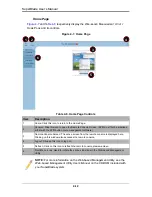
will then display as shown in
Figure 4-7
.
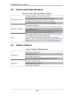
Address Defaults
Table 4-5
shows the default addresses that are initially set for the CMM. Afterwards, you
can change these values within the program (see the
Web-based Management Utility
User’s Manual
on your system’s enclosed CD-ROM for more details).
Table 4-5. Address Defaults
Default
Description
Default IP Address
192.168.100.100
Default Gateway Address
0.0.0.0
Default Subnet Mask
255.255.255.0
Default username
ADMIN
Default password
ADMIN
Summary of Contents for SuperBlade Series
Page 1: ...SuperBlade User s Manual Revison 1 0c...
Page 4: ...SuperBlade User s Manual iv Notes...
Page 8: ...SuperBlade User s Manual viii Notes...
Page 10: ...SuperBlade User s Manual x Notes...
Page 12: ...SuperBlade User s Manual xii Notes...
Page 22: ...SuperBlade User s Manual 1 10 Notes...
Page 30: ...SuperBlade User s Manual 3 6 Figure 3 4 Enclosure Installed into Rack...
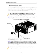
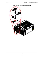
Page 53: ...5 7 Chapter 5 Power Supply Modules Figure 5 6 Power Cable Tie and Clamp Assembly...
Page 54: ...SuperBlade User s Manual 5 8 Notes...
Page 58: ...SuperBlade User s Manual A 4 Notes...

