
D-6
SC933 Chassis Manual
UPER
REV 3.00
SATA933
R
S
ON
DISABLE
ENABLE
ENABLE
FAN#2 FAN#1
FAN#3
FAN#4
ENABLE
ENABLE
DISABLE
DISABLE
DISABLE
OFF
JP61
JP62
JP63
JP64
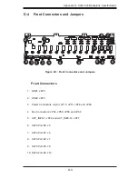
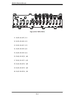
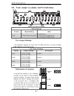
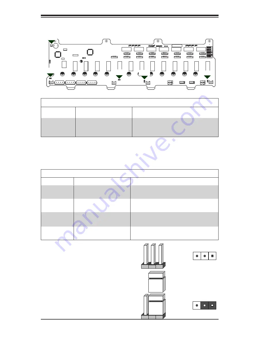
D-6 Front Jumper
Locations and Pin Definitions
Explanation of Jumpers
To modify the operation of the backplane,
jumpers can be used to choose between
optional settings. Jumpers create shorts
between two pins to change the function
of the connector. Pin 1 is identified with
a square solder pad on the printed circuit
board. Note: On two pin jumpers, "Closed"
means the jumper is on and "Open" means
the jumper is off the pins.
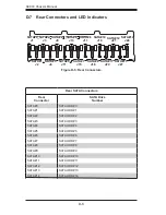
Connector
Pins
Jumper
Setting
3 2 1
3 2 1
JP63
JP64
Socket Settings
Socket
Socket Setting
Note
JP18
Connected to front panel
Buzzer Reset
Press once to disable buzzer;
Press twice to enable buzzer
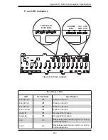
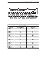
Fan Jumper Settings
This backplane supports up to four fans. To utilize each fan, you must configure
both jumpers
as instructed below.
Fan Jumper Settings
Jumper
Jumper Settings
Fan Number
JP61
1-2 On: Enable
2-3 Off: Disable
FAN #1
JP62
1-2 On: Enable
2-3 Off: Disable
FAN #2
JP63
1-2 On: Enable
2-3 Off: Disable
FAN #3
JP64
1-2 On: Enable
2-3 Off: Disable
FAN #4
JP62
JP61
JP18
Figure D-3: Front Jumpers