


SC936 Chassis Manual
4-6
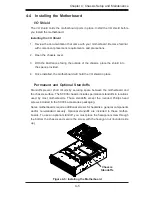
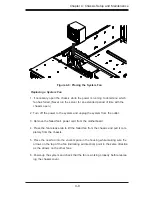
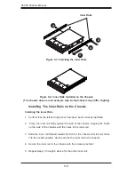
Installing the Motherboard
Review the documentation that came with your motherboard. Become familiar
1.
with component placement, requirements, precautions, and cable connec-
tions.
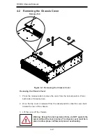
Open the chassis cover.
2.
As required by your motherboard, install standoffs in any areas that do not
3.
have a permanent standoff. To do this:
A. Place a hexagonal standoff screw through the bottom the chassis.
B. Secure the screw with the hexagon nut (rounded side up).
Lay the motherboard on the chassis aligning the permanent and optional
4.
standoffs
Secure the motherboard to the chassis using the rounded, Phillips head
5.
screws. Do not exceed 8 pounds of torque when tightening down the mother-
board.
Secure the CPU(s), heatsinks, and other components to the motherboard as
6.
described in the motherboard documentation.
Connect the cables between the motherboard, backplane, chassis, front pan-
7.
el, and power supply, as needed. Also, the fans may be temporarily removed
to allow access to the backplane ports.
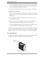
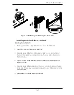
Add-on Card/Expansion Slot Setup
SC936 chassis include I/O slots for add-on cards and expansion cards. It provides
seven low-profile add-on card slots.
Installing Add-on and Expansion Cards
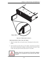
Disconnect the power supply, lay the chassis on a flat surface, and open the
1.
chassis cover.
Remove the screw holding the cover in place for each low profile add-on/ex
-
2.
pansion card slot you want to use. Keep this screw for later use.
Connect the add-on cards and/or expansion cards to the mother board.
3.
Secure each card to the chassis using the card's L bracket and the screw
4.
previously removed.
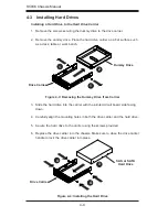
Summary of Contents for Supero SC936 Series
Page 18: ...SC936 Chassis Manual 3 4 Notes ...
Page 30: ...SC936 Chassis Manual 4 12 Notes ...
Page 40: ...SC936 Chassis Manual 5 10 Notes ...