
C-2
SC936 Chassis Manual
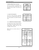
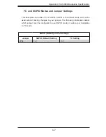
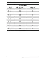
MH7
PWR0
PWR1
PWR2
PWR3
FAN1
FAN3
FAN2
SEC_I2C
R581
SAS936A
3.1
BAR CODE
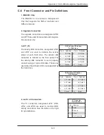
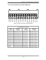
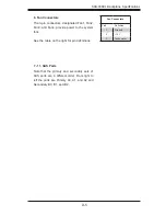
+5V
+12V
GND
GND
+5V
+12V
GND
GND
+5V
+12V
GND
GND
+5V
+12V
GND
GND
A
C
A
C
A
C
REV:
A
C
A
C
A
C
A
C
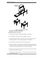
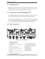
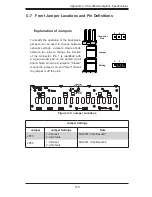
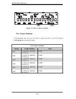
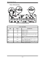
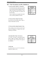
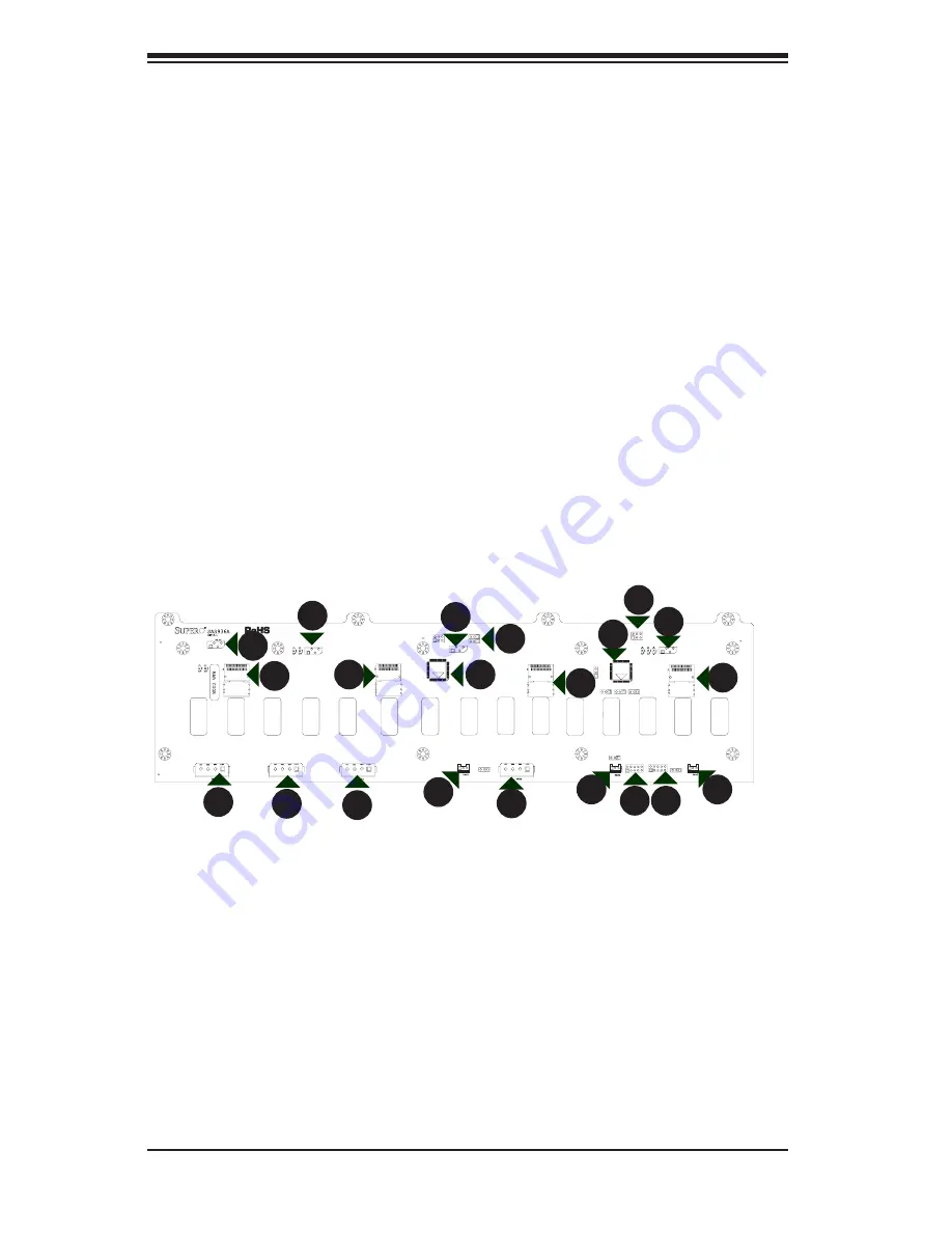
Front Connectors
Chip: MG9072
1.
Upgrade Connectors: JP69 and
2.
JP78
ACT_IN: JP26 and JP47
3.
I
4.
2
C Connector #1 (JP37) and #2
(JP95)
I
5.
2
C Connector #3 (JP52) and #4
(JP96)
Power Connectors (4-pin): JP10,
6.
JP13, JP46 and JP48.
Fan Connector, Fan#1 JP54
7.
Fan Connector, Fan#2 JP56
8.
Fan Connector, Fan#3 JP58
9.
SAS IN#1 JSM1
10.
SAS IN#2 JSM2
11.
SAS IN#3 JSM3
12.
SAS IN#4 JSM4
13.
C-3 A Note to Users
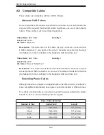
All images and layouts shown in this user's guide are based upon the latest revision
available at the time of publishing. The backplane you have received may or may
not look exactly the same as the graphics shown in this manual.
C-4 Introduction to the SAS-936A Backplane
The SAS-9836A backplane has been designed to utilize the most up-to-date technol-
ogy available, providing your system with reliable, high-quality performance.
This manual reflects SAS-936A Revision 3.1, the most current release available at
the time of publication. Always refer to the Supermicro Web site at www.supermicro.
com for the latest updates, compatible parts and supported configurations.
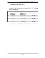
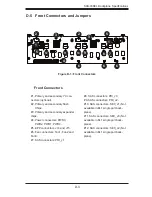
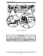
C-5 Front Connectors
Figure C-1: Front Connectors
1
1
1
1
1
9
1
8
1
7
1
6
1
6
1
6
1
6
1
5
1
5
1
4
1
3
1
3
1
2
1
2
1
10
1
12
1
13
1
11
1
4
Summary of Contents for Supero SC936 Series
Page 18: ...SC936 Chassis Manual 3 4 Notes ...
Page 30: ...SC936 Chassis Manual 4 12 Notes ...
Page 40: ...SC936 Chassis Manual 5 10 Notes ...