
C-3
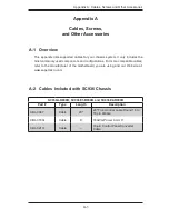
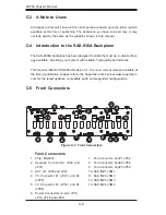
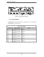
Appendix C: SAS-936A Backplane Specifications
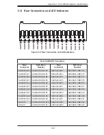
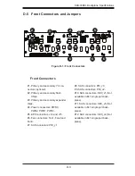
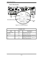
C-6 Front Connector and Pin Definitions
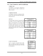
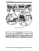
1. MG9072 Chip
The MG9072 is an enclosure management
chip that supports the SES-2 controller and
SES-2 protocols.
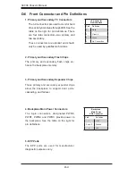
2. Upgrade Connectors
The upgrade connectors are designated JP69,
and JP78 are used for manufacturer's diagnos-
tic purposes only.
3. ACT_IN:
The activity LED connectors, designated JP26,
and JP47 are used to indicate the activity
status of each SAS drive. The activity LED
connector is located on the front panel. For
the activity LED connector to work properly,
connect using a 10-pin LED cable. This is only
used when the activity LED is not supported by
the hard drive.
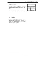
4. and 5. I
2
C Connectors
The I
2
C connectors, designated JP37, JP95,
JP52, and JP96 are used to monitor HDD
activity and status. See the table on the right
for pin definitions.
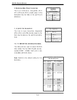
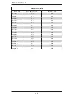
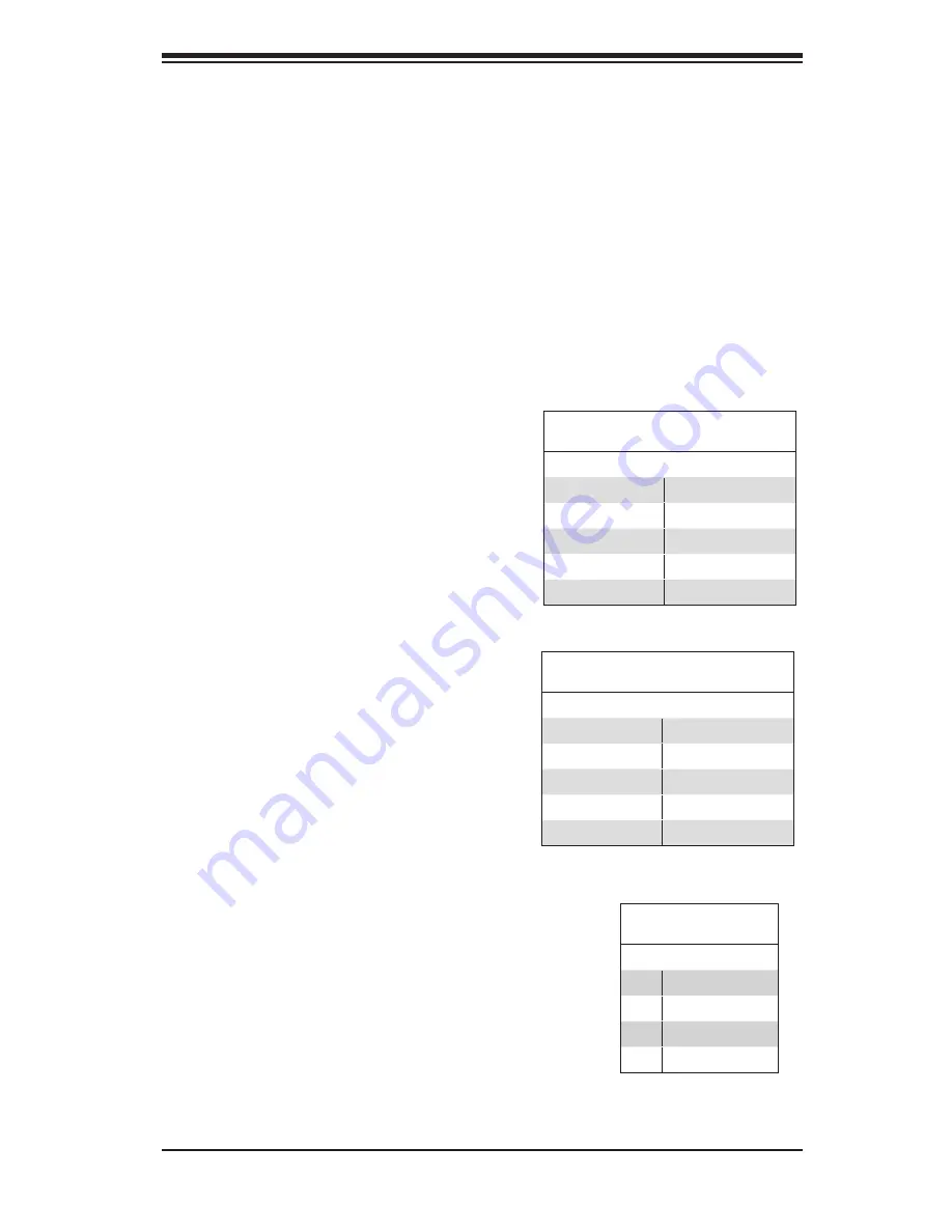
SAS Activity LED Header
Pin Definitions
Pin # Definition
Pin # Definition
1
ACT IN#0
6
ACT IN#4
2
ACT IN#1
7
ACT IN#5
3
ACT IN#2
8
ACT IN#6
4
ACT IN#3
9
ACT IN#7
5
Ground
10
Empty
SAS Activity LED Header
Pin Definitions
Pin # Definition
Pin # Definition
1
ACT IN#8
6
ACT IN#12
2
ACT IN#9
7
ACT IN#13
3
ACT IN#10
8
ACT IN#14
4
ACT IN#11
9
ACT IN#15
5
Ground
10
Empty
I
2
C Connector
Pin Definitions
Pin# Definition
1
Data
2
Ground
3
Clock
4
No Connection
Summary of Contents for Supero SC936 Series
Page 18: ...SC936 Chassis Manual 3 4 Notes ...
Page 30: ...SC936 Chassis Manual 4 12 Notes ...
Page 40: ...SC936 Chassis Manual 5 10 Notes ...


