


D-4
SC936 Chassis Manual
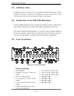
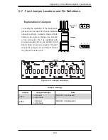
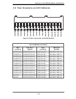
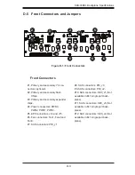
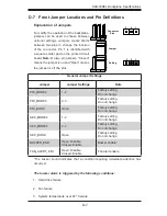
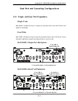
D-6 Front Connector and Pin Definitions
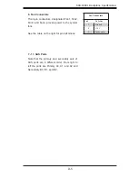
Backplane
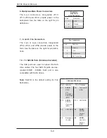
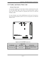
Main Power
4-Pin Connector
Pin# Definition
1
+12V
2 and 3
Ground
4
+5V
4. Backplane Main Power Connectors
The 4-pin connectors, designated PWR0,
PWR1, PWR2, and PWR3, provide power to
the backplane. See the table on the right for
pin definitions.
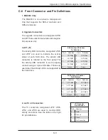
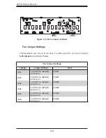
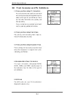
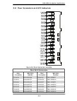
1. Primary and Secondary I
2
C Connectors
The I
2
C connectors are used to monitor hard
drive activity and status through LED. See the
table on the right for pin definitions. There
are four total connectors--two primary and
two secondary.
These connectors are optional and should
only be used by qualified technicians.
I
2
C Connector
Pin Definitions
Pin# Definition
1
Data
2
Ground
3
Clock
4
No Connection
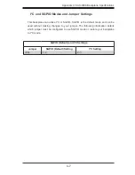
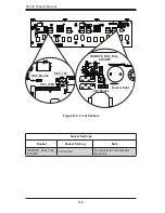
3. Primary and Secondary Expander Chips
These primary and secondary expander chips
allow the backplane to support dual ports,
cascading, and failover.
2. Primary and Secondary Flash Chips
The primary and secondary flash chips en
-
hance the backplane memory.
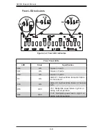
5. EPP Ports
The EPP ports are used for manufacturer
diagnostic purposes only.
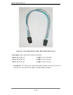
Summary of Contents for Supero SC936 Series
Page 18: ...SC936 Chassis Manual 3 4 Notes ...
Page 30: ...SC936 Chassis Manual 4 12 Notes ...
Page 40: ...SC936 Chassis Manual 5 10 Notes ...