background image

Chapter 6: Advanced Chassis Setup

6-1

Chapter 6 

Advanced Chassis Setup

This chapter covers the steps required to install components and perform mainte-

nance on the SC815TQ-R650U/SC815TQ-560U chassis. For component installa-

tion, follow the steps in the order given to eliminate the most common problems 

encountered. If some steps are unnecessary, skip ahead to the next step.

Tools Required: 

The only tool you will need to install components and perform 

maintenance is a Philips screwdriver.

6-1 Static-Sensitive 

Devices

Electrostatic discharge (ESD) can damage electronic com 

ponents. To prevent 

damage to any printed circuit boards (PCBs), it is important to handle them very 

carefully. The following measures are generally suffi cient to protect your equipment 

from ESD damage.

Precautions

Use a grounded wrist strap designed to prevent static discharge.

Touch a grounded metal object before removing any board from its antistatic 

bag.

Handle a board by its edges only; do not touch its components, peripheral chips, 

memory modules or gold contacts.

When handling chips or modules, avoid touching their pins.

Put the serverboard, add-on cards and peripherals back into their antistatic 

bags when not in use.

For grounding purposes, make sure your computer chassis provides excellent 

conductivity between the power supply, the case, the mounting fasteners and 

the serverboard.

Summary of Contents for SUPERSERVER 6015C-NT

Page 1: ...SUPERSERVER 6015C UR SUPERSERVER 6015C U SUPERSERVER 6015C NTR SUPERSERVER 6015C NT SUPER USER S MANUAL 1 0 ...

Page 2: ...FROM THE USE OR INABILITY TO USE THIS PRODUCT OR DOCUMENTATION EVEN IF ADVISED OF THE POSSIBILITY OF SUCH DAMAGES IN PARTICULAR SUPER MICRO SHALL NOT HAVE LIABILITY FOR ANY HARDWARE SOFTWARE OR DATA STORED OR USED WITH THE PRODUCT INCLUDING THE COSTS OF REPAIRING REPLACING INTEGRATING INSTALLING OR RECOVERING SUCH HARDWARE SOFTWARE OR DATA Any disputes arising between manufacturer and customer sha...

Page 3: ...ion Chapter 1 Introduction The first chapter provides a checklist of the main components included with the server system and describes the main features of the X7DCU serverboard and the SC815TQ R650U SC815TQ 560U chassis which comprise the SuperServer 6015C UR 6015C U 6015C NTR 6015C NT Chapter 2 Server Installation This chapter describes the steps necessary to install the SuperServer 6015C UR 6015...

Page 4: ...ders and jumpers Refer to this chapter when adding or removing processors or main memory and when reconfiguring the serverboard Chapter 6 Advanced Chassis Setup Refer to Chapter 6 for detailed information on the SC815TQ R650U SC815TQ 560U server chassis You should follow the procedures given in this chapter when installing removing or reconfiguring SATA or peripheral drives and when replacing system...

Page 5: ...v Preface Notes ...

Page 6: ... 1 4 1 4 Contacting Supermicro 1 6 Chapter 2 Server Installation 2 1 Overview 2 1 2 2 Unpacking the System 2 1 2 3 Preparing for Setup 2 1 Choosing a Setup Location 2 2 Rack Precautions 2 2 Server Precautions 2 2 Rack Mounting Considerations 2 3 Ambient Operating Temperature 2 3 Reduced Airflow 2 3 Mechanical Loading 2 3 Circuit Overloading 2 3 Reliable Ground 2 3 2 4 Installing the System into a R...

Page 7: ...eral Safety Precautions 4 2 4 3 ESD Precautions 4 3 4 4 Operating Precautions 4 4 Chapter 5 Advanced Serverboard Setup 5 1 Handling the Serverboard 5 1 Precautions 5 1 Unpacking 5 1 5 2 Processor and Heatsink Installation 5 2 5 3 Connecting Cables 5 5 Connecting Data Cables 5 5 Connecting Power Cables 5 5 Connecting the Control Panel 5 5 5 4 I O Ports 5 6 5 5 Installing Memory 5 7 5 6 Adding PCI C...

Page 8: ...Removal 6 4 Removing the Front Bezel 6 4 Accessing the Drive Bays 6 5 SATA Drive Installation 6 6 DVD ROM and Floppy Drive Installation 6 8 6 5 Power Supply 6 9 6015C UR 6015C NTR 6 9 Power Supply Failure 6 9 6015C U 6015C NT 6 10 Power Supply Failure 6 10 Chapter 7 BIOS 7 1 Introduction 7 1 7 2 Running Setup 7 2 7 3 Main BIOS Setup 7 2 7 4 Advanced Setup 7 6 7 5 Security 7 20 7 6 Boot 7 22 7 7 Ex...

Page 9: ...ets of 4 cm counter rotating fans FAN 0086L One 1 DVD cable CBL 0139L Two 2 passive CPU heatsinks SNK P0017 Riser Cards see Section 5 6 for details One 1 RSC R1UU E8R for PCI X card One 1 RSC R1UU UE8 for PCI E card 6015C UR 6015C U only One 1 RSC R1UU 2E8 for two PCI E cards 6015C NTR 6015C NT only SATA Accessories One 1 SATA backplane BPN SAS 815TQ One 1 SATA iPASS cable CBL 0188L 6015C UR 6015C...

Page 10: ...ry speed jumper settings UIO The X7DCU is a specially designed serverboard that features Supermicro s UIO Universal I O technology UIO serverboards have a PCI Express x8 connector that can support any one of several types of UIO card types to add SAS ports additional LAN ports etc to the serverboard This allows the user to tailor the serverboard to their own needs Note the 6025C UR does not come w...

Page 11: ...oes not need to be shut down when replacing or removing a single power supply module The SC815TQ 560U features a single 560W power supply module The system must be shut down when replacing or removing this power supply module SATA Subsystem The SC815TQ R650U SC815TQ 560U chassis was designed to support four hot swap SATA hard drives Note In the 6015C NTR 6015C NT SATA drives are connected to the o...

Page 12: ... to be used in a 1U rackmount configuration Ports on the I O backplane include one COM port a VGA port two USB 2 0 ports PS 2 mouse and keyboard ports and two gigabit Ethernet ports A UID Unit Identifier button and LED are also located beside the LAN2 Ethernet port Cooling System The SC815TQ R650U SC815TQ 560U chassis has an innovative cooling design that features four sets of 4 cm counter rotating ...

Page 13: ...nal SIO W83627 VGA PCI33MHz RN50 VGA CONN KB MS VRM 2 3 4 5 VRM Processor 1 1067 1333 MT S 1067 1333 MT S HF USB 0 1 2 3 4 PCIE x4 1C 1B DDR2 667 SATA 0 1 2 3 Ports 6 7 PCI E x8 2C 2B DDR2 667 4 5 ZOAR DMI Lanes 1 2 3 4 Lane 5 Lane 6 PCI E x4 COM2 Internal SOL RJ45 PCI E x8 UIO Right Hand Side PCI E x 16 UIO left hand side SIMSO CONN 2A 1A PCI32 33MHz DDR 2 16X16M AD17 PCI E x1 JMB368 IDE IDE SPI ...

Page 14: ...com Europe Address Super Micro Computer B V Het Sterrenbeeld 28 5215 ML s Hertogenbosch The Netherlands Tel 31 0 73 6400390 Fax 31 0 73 6416525 Email sales supermicro nl General Information support supermicro nl Technical Support rma supermicro nl Customer Support Asia Pacific Address Super Micro Computer Inc 4F No 232 1 Liancheng Rd Chung Ho 235 Taipei County Taiwan R O C Tel 886 2 8226 3990 Fax 8...

Page 15: ...maged in any way If the server itself shows damage you should file a damage claim with the carrier who delivered it Decide on a suitable location for the rack unit that will hold the 6015C UR 6015C U 6015C NTR 6015C NT It should be situated in a clean dust free area that is well ventilated Avoid areas where heat electrical noise and electromagnetic fields are generated You will also need it placed n...

Page 16: ...n the bottom of the rack are fully extended to the floor with the full weight of the rack resting on them In single rack installation stabilizers should be attached to the rack In multiple rack installations the racks should be coupled together Always make sure the rack is stable before extending a component from the rack You should extend only one component at a time extending two or more si multa...

Page 17: ...Equipment should be mounted into a rack so that the amount of airflow required for safe operation is not compromised Mechanical Loading Equipment should be mounted into a rack so that a hazardous condition does not arise due to uneven mechanical loading Circuit Overloading Consideration should be given to the connection of the equipment to the power supply circuitry and the effect that any possible...

Page 18: ...lation instructions that came with the rack unit you are using Identifying the Sections of the Rack Rails You should have received two rack rail assemblies in the rack mounting kit Each assembly consists of two sections an inner fixed chassis rail that secures directly to the server chassis and an outer fixed rack rail that secures directly to the rack itself see Figure 2 1 Two pairs of short bracke...

Page 19: ... bracket to the front side of the outer rail with two screws and the long bracket to the rear side of the outer rail with three screws Repeat these steps for the left outer rail Locking Tabs Both chassis rails have a locking tab which serves two functions The first is to lock the server into place when installed and pushed fully into the rack which is its normal position Secondly these tabs also lo...

Page 20: ...nd the rack unit The next step is to install the server into the rack Do this by lining up the rear of the chassis rails with the front of the rack rails Slide the chassis rails into the rack rails keeping the pressure even on both sides you may have to depress the locking tabs when inserting See Figure 2 3 When the server has been pushed completely into the rack you should hear the locking tabs c...

Page 21: ...tal First determine how far follow the server will extend out the front of the rack Larger chassis should be positioned to balance the weight between front and back If a bezel is included on your server remove it Then attach the two front brackets to each side of the chassis then the two rear brackets positioned with just enough space to accom modate the width of the telco rack Finish by sliding t...

Page 22: ...of the server See Figure 2 5 To remove the system from the rack completely depress the locking tabs in the chassis rails push the right side tab down and the left side tab up to continue to pull the system out past the locked position Checking the Components You may have one or two processors already installed in the serverboard Each processor needs its own heatsink See Chapter 5 for instructions ...

Page 23: ...server For servicing the DVD ROM and floppy drives you will need to remove the top chassis cover The SATA disk drives can be installed and removed from the front of the chassis without removing the top chassis cover A slim DVD ROM and floppy drive should be preinstalled in your server Refer to Chapter 6 if you need to reinstall a DVD ROM and or floppy disk drive to the system Depending upon your syst...

Page 24: ... airflow to the components that generate the most heat Note that all power and data cables have been routed in such a way that they do not block the airflow generated by the fans Providing Power The last thing you must do is to provide input power to the system Plug the power cords from the power supply modules into a high quality power strip that offers protection from electrical noise and power su...

Page 25: ...chapter explains the meanings of all LED indicators and the appropriate response you may need to take 3 2 Control Panel Buttons There are three push buttons located on the front of the chassis a reset button a UID button and a power on off button UID Depressing the UID unit identifier button illuminates an LED on both the front and rear of the chassis for easy system location in large stack configur...

Page 26: ... Fail Solid Blue Local UID Button Depressed Blinking Blue IPMI Activated UID Note deactivating the UID LED must be performed in the same way it was activated If the UID LED was activated via IPMI you can only turn the LED off via IPMI and not with the UID button Universal Information LED When this LED blinks red quickly it indicates a fan failure and when blinking red slowly a power failure The LE...

Page 27: ...n LAN1 when flashing HDD Indicates IDE channel activity On the SuperServer 6015C UR 6015C U 6015C NTR 6015C NT this light indicates SATA and or DVD ROM drive activity when flashing Power Indicates power is being supplied to the system s power supply units This LED should normally be illuminated when the system is operating ...

Page 28: ...drive activity A connection to the drive backplane enables this LED to blink on and off when that particular drive is being accessed Red The red LED indicates two states When blinking it indicates the drive is rebuilding When solid it indicates a drive failure If a hard drive fails you should be notified by your system management software Please refer to Chapter 6 for instructions on replacing fail...

Page 29: ...isconnecting power you should first power down the system with the operating system first and then unplug the power cords of all the power supply units in the system When working around exposed electrical circuits another person who is familiar with the power off controls should be nearby to switch off the power if neces sary Use only one hand when working with powered on electrical equipment This i...

Page 30: ...elry or metal objects from your body which are excellent metal conductors that can create short circuits and harm you if they come into contact with printed circuit boards or areas where power is present Serverboard Battery CAUTION There is a danger of explosion if the onboard battery is installed upside down which will reverse its polarites see Figure 4 1 This battery must be replaced only with t...

Page 31: ...il ready for use Touch a grounded metal object before removing the board from the antistatic bag Do not let components or PCBs come into contact with your clothing which may retain a charge even if you are wearing a wrist strap Handle a board by its edges only do not touch its components peripheral chips memory modules or contacts When handling chips or modules avoid touching their pins Put the se...

Page 32: ...sure that the chassis cover is in place when the 6015C UR 6015C U 6015C NTR 6015C NT is operating to assure proper cooling Out of warranty damage to the system can occur if this practice is not strictly followed Figure 4 1 Installing the Onboard Battery LITHIUM BATTERY BATTERY HOLDER BATTERY HOLDER LITHIUM BATTERY OR ...

Page 33: ...at the size and weight of the serverboard can cause it to bend if handled improperly which may result in damage To prevent the serverboard from bending keep one hand under the center of the board to support it when handling The following measures are generally sufficient to protect your equipment from static discharge Precautions Use a grounded wrist strap designed to prevent static discharge Touch...

Page 34: ...sing a Xeon CPU or when receiving a serverboard with a CPU pre installed make sure that the CPU plastic cap is in place and none of the CPU pins are bent otherwise contact the retailer immediately 5 2 Processor and Heatsink Installation When handling the processor avoid placing direct pressure on the label area of the fan Also do not place the serverboard on a conductive sur face which can damage ...

Page 35: ...y or vertically and do not rub the CPU against any surface or any of the contacts which may damage the CPU and or contacts 7 With the CPU in the socket inspect the four corners of the CPU to make sure that it is properly installed 8 Use your thumb to gently push the load lever down until it snaps into the retention clasp 9 If the CPU is properly installed into the socket the PnP cap will be auto m...

Page 36: ...on mechanism 3 Screw in two diagonal screws i e the 1 and the 2 screws until just snug Do not fully tighten the screws or you may damage the CPU 4 Add the two remaining screws then finish the installation by fully tightening all four screws Removing the Heatsink 1 Unscrew and remove the heatsink screws from the serverboard in the sequence as show in the picture above 2 Hold the heatsink and gently ...

Page 37: ...e serverboard layout diagram in this chapter for connector locations DVD ROM Drive cable IDE Control Panel cable JF1 see next page SATA cables SATA0 SATA3 Connecting Power Cables The X7DCU has a 20 pin primary power supply connector designated JPW1 for connection to the ATX power supply Connect the appropriate connector from the power supply to JPW1 to supply power to the serverboard See the Conne...

Page 38: ...apter for details and pin descrip tions of JF1 NMI x key Vcc UID Switch Vcc Vcc Vcc Vcc Vcc Reset Power Ground x key Power LED HDD LED NIC1 NIC2 OH Fan Fail UID LED Power Fail LED Ground Ground 2 1 20 19 5 4 I O Ports The I O ports are color coded in conformance with the PC 99 specification See Figure 5 2 below for the colors and locations of the various I O ports Figure 5 2 Rear Panel I O Ports Mo...

Page 39: ...module incor rectly see Figure 5 5 Gently press down on the DIMM module until it snaps into place in the slot Repeat for all modules see step 1 above Install DIMMs in the following order DIMM1A and DIMM2A then DIMM1B and DIMM2B and finally DIMM1C and DIMM2C Memory Support The X7DCU supports up to 48 GB of ECC DDR2 667 or DDR2 533 SDRAM The memory is an interleaved configuration which requires module...

Page 40: ... receptive point on the slot Notch Notch Release Tab Release Tab Possible System Memory Allocation Availability System Device Size Physical Memory Remaining 4 GB Total System Memory Firmware Hub flash memory System BIOS 1 MB 3 99 Local APIC 4 KB 3 99 Area Reserved for the chipset 2 MB 3 99 I O APIC 4 Kbytes 4 KB 3 99 PCI Enumeration Area 1 256 MB 3 76 PCI Express 256 MB 256 MB 3 51 PCI Enumeration ...

Page 41: ...low PCI Card Installation Before installing a PCI add on card make sure you install it into the correct riser card Begin by releasing the locking tab that corresponds to the slot you wish to populate Insert the expansion card into the correct riser card pushing down with your thumbs evenly on both sides of the card PCI Slot Card Configurations 6015C UR 6015C U Left Side Riser Card Expansion card su...

Page 42: ...FAN6 FAN5 FAN7 JWF1 I SATA0 CPU2 CPU1 SXB2 PCI E X8 UIOP BANK3 JWOL SGPIO2SGPIO1 COM2 CPU FAN1 KB MS SMBUS_PS COM1 USB0 1 BANK2 LAN1 VGA BANK1 DIMM2C DIMM1B DIMM2A DIMM2B DIMM1A LAN2 CPU FAN2 Compact Flash IDE Floppy SXB1 PCI E X16 USB 4 USB 2 3 JPEW1 Battery DIMM1C SIMSO IPMI VGA CTRL LAN CTRL Intel 5100 North Bridge Intel ICH9R South Bridge USB5 LE19 X7DCU S I O I SATA1 I SATA2 I SATA3 I SATA4 I...

Page 43: ...tor I SATA0 I SATA5 SATA Ports JD1 Onboard Speaker Power LED JF1 Control Panel Connector JK1 Keylock Header JL1 Chassis Intrusion Header JOH1 Overheat Warning Header JPW1 20 Pin ATX Power Connector JPW2 4 Pin Power Connector JPW3 8 pin Processor Power Connector JWOL1 Wake On LAN Header JWOR Wake On Ring Header LAN1 2 Gigabit Ethernet RJ45 Ports SIMSO IPMI SIMSO IPMI Remote Management Slot SGPIO 1 ...

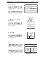
Page 44: ...imary ATX power connector above the Auxiliary 4 pin connector at JPW2 must also be con nected to your power supply See the table on the right for pin definitions NMI Button Pin Definitions JF1 Pin Definition 19 Control 20 Ground Processor Power Pin Definitions JPW3 Pins Definition 1 through 4 Ground 5 through 8 12V Auxiliary Power Pin Definitions JPW2 Pins Definition 1 2 Ground 3 4 12V Power LED Pin Defin...

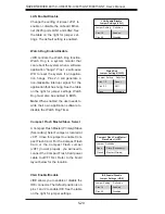
Page 45: ... on pins 13 and 14 of JF1 Attach the IDE hard drive LED cable to display disk activity Refer to the table on the right for pin definitions HDD LED Pin Definitions JF1 Pin Definition 13 Vcc 14 HD Active Universal Information LED Connect an LED to pins 7 and 8 of JF1 to provide advanced warning of chassis overheating or fan failure These pins also work with the front UID indicator which will activate a...

Page 46: ...epress the button for at least 4 seconds Refer to the table on the right for pin definitions Universal Serial Bus Ports Two Universal Serial Bus ports are located on the I O backplane USB0 is the bottom connector and USB1 is the top connector USB5 is a port located near the USB4 header See the table on the right for pin definitions Reset Button Pin Definitions JF1 Pin Definition 3 Reset 4 Ground Power...

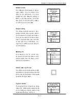
Page 47: ...ns COM1 COM2 Pin Definition Pin Definition 1 DCD 6 DSR 2 RXD 7 RTS 3 TXD 8 CTS 4 DTR 9 RI 5 Ground 10 NC Fan Header Pin Definitions FAN1 8 Pin Definition 1 Ground Black 2 12V Red 3 Tachometer 4 PWM Control Universal Serial Bus Headers Three additional USB headers USB2 USB3 and USB4 are included on the serverboard These may be used for front side access A USB cable not included is needed for the connec...

Page 48: ... VCC 5 Clock 6 NC Speaker Connector Pin Definitions JD1 Pin Function Definition 4 Speaker data red wire 5 Key No connection 6 Key 7 Speaker data Overheat LED Connect an LED to the JOH1 header to provide warning of a chassis overheat ing condition See the table on the right for pin definitions Overheat LED Pin Definitions JOH1 Pin Definition 1 5V 2 OH Active SGPIO The two headers labeled SGPIO 1 and SGP...

Page 49: ...ke On Ring Pin Definitions JWOR Pin Definition 1 Ground Black 2 Wake up Wake On LAN Pin Definitions JWOL1 Pin Definition 1 5V Standby 2 Ground 3 Wake up SMBUS_PS This header is for I2 C which may be used to monitor the status of the power supply See the table on the right for pin definitions SMBUS_PS I2 C Pin Definitions Pin Definition 1 Clock 2 SMB Data 3 N A 4 N A 5 N A LAN1 2 Ethernet Ports Two Ethern...

Page 50: ...nel UID Switch connects to pin 13 of JF1 The Rear UID Switch SW1 is located next to LAN2 Push ing the UID switch on the Front Control Panel will illuminate both the Rear UID and the Control Panel UID indicators Push the either switch again to turn off both indicators These UID indicators provide easy identification of a system that may be in need of service ...

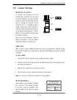
Page 51: ...o clear CMOS and will also clear any passwords Instead of pins this jumper consists of contact pads to prevent accidentally clearing the contents of CMOS To clear CMOS First power down the system and unplug the power cord s With the power disconnected short the CMOS pads with a metal object such as a small screwdriver Remove the screwdriver or shorting device Reconnect the power cord s and power o...

Page 52: ...Watch Dog Timer LAN Enable Disable Jumper Settings JPL1 Jumper Setting Definition Pins 1 2 Enabled Pins 2 3 Disabled Watch Dog Jumper Settings JWD Jumper Setting Definition Pins 1 2 Reset Pins 2 3 NMI Open Disabled Compact Flash Master Slave Select A Compact Flash Master Primary Slave Secondary Select Jumper is located at JCF1 Close this jumper to enable Com pact Flash Card For the Compact Flash Car...

Page 53: ... 100 MHz Amber 1 GHz LE19 The LE1 LED located near JF1 is the power LED LE19 illuminates when the serverboard is powered up Be sure to remove the poower cable when install ing or removing any components LE2 The LE2 LED located under SW1 is the UID indicator LED LE2 illuminates when UID is initiated either by the UID button or via IPMI If initiated a second time LE2 will turn off When the LED blink...

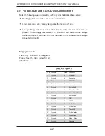
Page 54: ...onnects to drive A and the connector that does not have twisted wires always connects to drive B Floppy Connector The floppy connector is designated Floppy See the table below for pin definitions Floppy Drive Connector Pin Definitions Floppy Pin Definition Pin Definition 1 Ground 2 FDHDIN 3 Ground 4 Reserved 5 Key 6 FDEDIN 7 Ground 8 Index 9 Ground 10 Motor Enable 11 Ground 12 Drive Select B 13 Ground ...

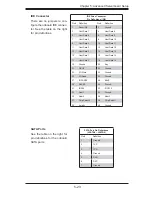
Page 55: ...ost Data 11 11 Host Data 3 12 Host Data 12 13 Host Data 2 14 Host Data 13 15 Host Data 1 16 Host Data 14 17 Host Data 0 18 Host Data 15 19 Ground 20 Key 21 DRQ3 22 Ground 23 I O Write 24 Ground 25 I O Read 26 Ground 27 IOCHRDY 28 BALE 29 DACK3 30 Ground 31 IRQ14 32 IOCS16 33 Addr1 34 Ground 35 Addr0 36 Addr2 37 Chip Select 0 38 Chip Select 1 39 Activity 40 Ground SATA Ports See the table on the ri...

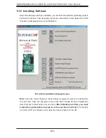
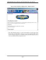
Page 56: ...t came packaged with your motherboard Driver Tool Installation Display Screen Note Click the icons showing a hand writing on paper to view the readme files for each item Click the computer icons to the right of these items to install each item from top to the bottom one at a time After installing each item you must re boot the system before moving on to the next item on the list The bottom icon wit...

Page 57: ...ucial system information such as CPU temperature system voltages and fan status See the Figure below for a display of the Supero Doctor III interface Note The default User Name and Password for SuperDoctor III is ADMIN AD MIN Note When SuperDoctor III is first installed it adopts the temperature threshold settings that have been set in BIOS Any subsequent changes to these thresholds must be made wi...

Page 58: ... can be downloaded from our Web Site at ftp ftp supermicro com utility Supero_Doctor_III You can also download SDIII User s Guide at http www supermicro com PRODUCT Manuals SDIII UserGuide pdf For Linux we will still recommend Supero Doctor II Supero Doctor III Interface Display Screen Remote Control ...

Page 59: ...s To prevent damage to any printed circuit boards PCBs it is important to handle them very carefully The following measures are generally sufficient to protect your equipment from ESD damage Precautions Use a grounded wrist strap designed to prevent static discharge Touch a grounded metal object before removing any board from its antistatic bag Handle a board by its edges only do not touch its comp...

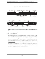
Page 60: ...n the Control Panel PCB printed circuit board Make sure the red wire plugs into pin 1 on both connectors Pull all excess cabling out of the airflow path The control panel LEDs inform you of system status See Chapter 3 System In terface for details on the LEDs and the control panel buttons Details on JF1 can be found in Chapter 5 Advanced Serverboard Setup Control Panel System LEDs Main Power Slim F...

Page 61: ...ystem can continue to run with a failed fan Remove the top chassis cover while the system is still running to determine which of the two fans has failed Then power down the system before replacing a fan Removing the power cords is also recommended as a safety precaution Replacing System Fans After determining which fan has failed turn off the power to the system Unplug the fan cable from the mothe...

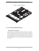
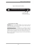
Page 62: ...you must first remove it to gain access to the drive bays To remove the bezel first unlock the front of the chassis then press the release knob see Figure 6 3 Carefully re move the bezel with both hands A filter located within the bezel can be removed for replacement cleaning It is recommended that you keep a maintenance log of filter cleaning replacement since its condition will affect the airflow thr...

Page 63: ...ppy Disk Drives For installing removing a DVD ROM or floppy disk drive you will need to gain access to the inside of the 6015C UR 6015C U 6015C NTR 6015C NT by removing the top cover of the chassis Proceed to the DVD ROM and Floppy Drive Installation section later in this chapter for instructions Note Only slim DVD ROM and floppy drives will fit into the 6015C UR 6015C U 6015C NTR 6015C NT Figure 6 3...

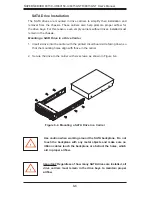
Page 64: ...nsert a drive into the carrier with the printed circuit board side facing down so that the mounting holes align with those in the carrier Secure the drive to the carrier with six screws as shown in Figure 6 4 1 2 Figure 6 4 Mounting a SATA Drive in a Carrier Important Regardless of how many SATA drives are installed all drive carriers must remain in the drive bays to maintain proper airflow Use cau...

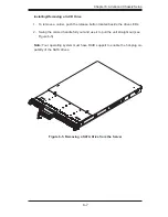
Page 65: ...the release button located beside the drive LEDs Swing the colored handle fully out and use it to pull the unit straight out see Figure 6 5 Note Your operating system must have RAID support to enable the hot plug ca pability of the SATA drives 1 2 Figure 6 5 Removing a SATA Drive from the Server ...

Page 66: ...er from the chassis to gain full access to the inside of the server Removing Installing a Drive With the chassis cover removed unplug the power and data cables from the drive you want to remove Locate the locking tab at the rear of the drive It will be on the left side of the drive when viewed from the front of the chassis Pull the tab away from the drive and push the drive unit out the front of t...

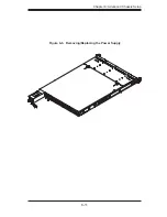
Page 67: ...placement modules can be ordered directly from Supermicro see contact information in the Preface The power supply modules have a hot swap capability meaning you can replace the failed module without powering down the system Replacing the Power Supply You do not need to shut down the system to replace a power supply module The redundant feature will keep the system up and running while you replace ...

Page 68: ...ore removing and replacing the power supply for whatever reason Replacing the Power Supply First turn the power switch on the control panel off then unplug the power cord from the system Replace with the same model p n PWS 561 1H20 which can be ordered directly from Supermicro see Contact Information in the Preface Remove the screws that secure the power supply to the chassis then pull the module ...

Page 69: ...Chapter 6 Advanced Chassis Setup 6 11 Figure 6 6 Removing Replacing the Power Supply ...

Page 70: ...6 12 SUPERSERVER 6015C UR 6015C U 6015C NTR 6015C NT User s Manual Notes ...

Page 71: ... a backup battery pro vides power to the CMOS Logic enabling it to retain system parameters Each time the computer is powered on the computer is configured with the values stored in the CMOS Logic by the system BIOS which gains control at boot up How To Change the Configuration Data The CMOS information that determines the system parameters may be changed by entering the BIOS Setup utility This Setu...

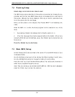
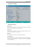
Page 72: ...f two ways 1 By pressing Delete immediately after turning the system on or 2 When the message shown below appears briefly at the bottom of the screen during the POST Power On Self Test press the Delete key to activate the main Setup menu Press the Delete key to enter Setup 7 3 Main BIOS Setup All main Setup options are described in this section The main BIOS Setup screen is displayed below Use the...

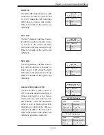
Page 73: ...ate Using the arrow keys highlight the month day and year fields and enter the correct data Press the Enter key to save the data BIOS Date This field displays the date when this version of BIOS was built Legacy Diskette A This setting allows the user to set the type of floppy disk drive installed as diskette A The options are Disabled 360Kb 5 25 in 1 2MB 5 25 in 720Kb 3 5 in 1 44 1 25MB 3 5 in and 2 ...

Page 74: ...Auto will allow the BIOS to automatically configure the parameters of the HDD installed at the connection Enter a number between 1 to 39 to select a predetermined HDD type Select User to allow the user to enter the parameters of the HDD installed Select CDROM if a CDROM drive is installed Select ATAPI if a removable disk drive is installed Multi Sector Transfers This item allows the user to specify...

Page 75: ...are Parallel ATA Serial ATA Both and Auto SATA Controller Mode Select Compatible to allow the SATA and PATA drives to be automatically detected and be placed in the Legacy Mode by the BIOS Select Enhanced to allow the SATA and PATA drives to be to be automatically detected and be placed in the Native IDE Mode Note The Enhanced mode is supported by Windows 2000 OS or later versions When the SATA Co...

Page 76: ...nus that can be accessed by highlighting the item and pressing Enter Boot Features Access the submenu to make changes to the following settings QuickBoot Mode If enabled this feature will speed up the POST Power On Self Test routine by skipping certain tests after the computer is turned on The settings are Enabled and Disabled If Disabled the POST routine will run at normal speed QuietBoot Mode Th...

Page 77: ...an incoming call is received by your modem The options are On and Off Power Loss Control This setting allows you to choose how the system will react when power returns after an unexpected loss of power The options are Stay Off Power On and Last State Watch Dog If enabled this option will automatically reset the system if the system is not active for more than a predefi ned time period The options a...

Page 78: ... operations Select Uncached to disable this function Select Write Through to allow data to be cached into the buffer and written into the system memory at the same time Select Write Protect to prevent data from being written into the base memory area of Block 0 512K Select Write Back to allow the CPU to write data back directly from the buffer without writing data to the System Memory for fast CPU...

Page 79: ... Registers are configured as distinct separate units and cannot be overlapped If enabled the user can achieve better graphic effects when using a Linux graphic driver that requires the write combining configuration with 4GB or more memory The options are Enabled and Disabled PCI Configuration Access the submenu to make changes to the following settings for PCI devices Onboard GLAN1 GLAN2 OPROM Configu...

Page 80: ...iming may cause the system become unstable When this occurs reset the setting to the default setting Clock Spectrum Feature If Enabled the BIOS will monitor the level of Electromagnetic Interference caused by the components and will attempt to decrease the interference whenever needed The options are Enabled and Disabled Crystal Beach Features This feature cooperates with the Intel I O AT Accelera...

Page 81: ...for ECC memory correction Patrol Scrubbing Scrubbing is a process that allows the North Bridge to correct correctable memoryer rors detected on a memory module and send the correction to the requestor the original source When this item is set to Enabled the North Bridge will read and write back one cache line every 16K cycles if there is no delay caused by internal processing By using this method ...

Page 82: ...al Management 2 TM2 which will lower CPU voltage and frequency when the CPU temperature reaches a predefi ned overheat thresh old Set to Disabled to use Thermal Manager 1 TM1 allowing CPU clocking to be regulated via CPU Internal Clock modulation when the CPU temperature reaches the overheat threshold C1 Enhanced Mode Available if supported by the CPU Set to Enabled to enable Enhanced Halt State to...

Page 83: ...ge to this setting you will need to power off and restart the system for the change to take effect Please refer to Intel s web site for detailed information Intel EIST Support Available if supported by the CPU Select Enabled to use the Enhanced Intel SpeedStep Technology and allows the system to automatically adjust processor voltage and core frequency in an effort to reduce power consumption and ...

Page 84: ...e IRQ interrupt request for serial port A The options are IRQ3 and IRQ4 Serial Port B This setting allows you to assign control of serial port B The options are Enabled user defined Disabled Auto BIOS controlled and OS Controlled Mode This setting allows you to set the type of device that will be connected to serial port B The options are Normal and IR for an infrared device Base I O Address This s...

Page 85: ...ging This setting allows you to Enable or Disable event logging ECC Event Logging This setting allows you to Enable or Disable ECC event logging Mark DMI Events as Read Highlight this item and press Enter to mark the DMI events as read Clear All DMI Event Logs Select Yes and press Enter to clear all DMI event logs The options are Yes and No Console Redirection Access the submenu to make changes to...

Page 86: ...bled the BIOS will automatically display the status of the fans indicated in this item Fan Speed Control Modes This feature allows the user to decide how the system controls the speeds of the onboard fans The CPU temperature and the fan speed are correlative When the CPU on die temperature increases the fan speed will also increase and vice versa If the option is set to 3 pin fan the fan speed is ...

Page 87: ...ke prece dence over the BIOS settings When fi rst installed Supero Doctor III adopts the temperature threshold settings previously set in the BIOS Any subsequent changes to these thresholds must be made within Supero Doctor since the SD III settings override the BIOS settings For the Windows OS to adopt the BIOS temperature threshold settings please change the SDIII settings to be the same as those...

Page 88: ...le IPMI Event Logging When this function is set to Disabled the system will continue to log events received via system interface The options are Enabled and Disabled Clear System Event Logging Enabling this function to force the BIOS to clear the system event logs during the next cold boot The options are Enabled and Disabled Existing Event Log Number This item displays the number of the existing ...

Page 89: ...inutes This feature allows the user to set the time value in minutes for the previous item OS Boot Watch Dog by keying in a desired number in the blank The default set ting is 10 minutes Please ignore this option when OS Boot Watch Dog is set to Disabled Time Out Option This feature allows the user to determine what action to take in an event of a system boot failure The options are No Action Rese...

Page 90: ... temperatures fan speeds and voltages of various components 7 5 Security Choose Security from the Phoenix BIOS Setup Utility main menu with the arrow keys You should see the following display Security setting options are displayed by highlighting the setting using the arrow keys and pressing Enter All Security BIOS settings are described in this section ...

Page 91: ... has not been used and Set means a user password has been entered for the system Set Supervisor Password When the item Set Supervisor Password is highlighted hit the Enter key When prompted type the Supervisor s password in the dialogue box to set or to change supervisor s password which allows access to the BIOS Set User Password When the item Set User Password is highlighted hit the Enter key Wh...

Page 92: ... the boot list section above are bootable devices listed in the sequence of boot order as specified The boot functions for the devices included in the candidate list above are currently disabled Use a key or a key to move the device up or down Use the f key or the r key to specify the type of an USB device either fixed or removable You can select one item from the boot list and hit the x key to remo...

Page 93: ... changes you made and to exit the BIOS Setup utility Exit Discarding Changes Highlight this item and hit Enter to exit the BIOS Setup utility without saving any changes you may have made Load Setup Defaults Highlight this item and hit Enter to load the default settings for all items in the BIOS Setup These are the safest settings to use Discard Changes Highlight this item and hit Enter to discard ...

Page 94: ...7 24 SUPERSERVER 6015C UR 6015C U 6015C NTR 6015C NT User s Manual Save Changes Highlight this item and hit Enter to save any changes you made You will remain in the Setup utility ...

Page 95: ...d Keyboard controller failed test May require replacing keyboard controller Keyboard locked Unlock key switch Unlock the system to proceed Monitor type does not match CMOS Run SETUP Monitor type not correctly identified in Setup Shadow Ram Failed at offset nnnn Shadow RAM failed at offset nnnn of the 64k block at which the error was de tected System RAM Failed at offset nnnn System RAM failed at of...

Page 96: ...ailure was caused by incorrect values and they are not corrected the next boot will likely fail On systems with control of wait states improper Setup settings can also terminate POST and cause this error on the next boot Run Setup and verify that the waitstate configuration is correct This error is cleared the next time the system is booted Memory Size found by POST differed from CMOS The memory si...

Page 97: ...takes too long device Address Conflict Address conflict for specified device Allocation Error for device Run ISA or EISA Configuration Utility to resolve resource conflict for the specified device CD ROM Drive CD ROM Drive identified Entering SETUP Starting Setup program Failing Bits nnnn The hex number nnnn is a map of the bits at the RAM address which failed the memory test Each 1 one in the map indica...

Page 98: ...ting system not found Operating system cannot be located on either drive A or drive C Enter Setup and see if fixed disk and drive A are properly identified Parity Check 1 nnnn Parity error found in the system bus BIOS attempts to locate the address and display it on the screen If it cannot locate the address it displays Parity is a method for checking errors in binary data A parity error indicates t...

Page 99: ... devices have the Configuration Request bit set in the LCT Run an I2O Configuration Utility e g the SAC utility System BIOS shadowed System BIOS copied to shadow RAM UMB upper limit segment address nnnn Displays the address nnnn of the upper limit of Upper Memory Blocks indicating released segments of the BIOS which can be reclaimed by a virtual memory man ager Video BIOS shadowed Video BIOS success...

Page 100: ...A 6 SUPERSERVER 6015C UR 6015C U 6015C NTR 6015C NT User s Manual Notes ...
Page 101: ...the error to port 80h attempt to initialize video and write the error in the top left corner of the screen The following is a list of codes that may be written to port 80h POST Code Description 01h IPMI Initialization 02h Verify Real Mode 03h Disable Non Maskable Interrupt NMI 04h Get CPU type 06h Initialize system hardware 07h Disable shadow and execute code from the ROM 08h Initialize chipset wi...

Page 102: ...ize Phoenix Dispatch Manager 36h Warm start shut down 38h Shadow system BIOS ROM 3Ah Auto size cache 3Ch Advanced configuration of chipset registers 3Dh Load alternate registers with CMOS values 41h Initialize extended memory for RomPilot optional 42h Initialize interrupt vectors 45h POST device initialization 46h 2 1 2 3 Check ROM copyright notice 48h Check video configuration against CMOS 49h Init...

Page 103: ... 81h Late POST device initialization 82h Detect and install external RS232 ports 83h Configure non MCD IDE controllers 84h Detect and install external parallel ports 85h Initialize PC compatible PnP ISA devices 86h Re initialize onboard I O ports 87h Configure Motherboard Configurable Devices optional 88h Initialize BIOS Data Area 89h Enable Non Maskable Interrupts NMIs 8Ah Initialize Extended BIOS D...

Page 104: ...ietBoot optional B6h Check password optional B7h Initialize ACPI BIOS and PPM Structures B9h Prepare Boot BAh Initialize SMBIOS BCh Clear parity checkers BDh Display MultiBoot menu BEh Clear screen optional BFh Check virus and backup reminders C0h Try to boot with INT 19 C1h Initialize POST Error Manager PEM C2h Initialize error logging C3h Initialize error display function C4h Initialize system e...

Page 105: ...e interrupt vectors F1h Initialize Run Time Clock F2h Initialize video F3h Initialize System Management Manager F4h Output one beep F5h Clear Huge Segment F6h Boot to Mini DOS F7h Boot to Full DOS If the BIOS detects error 2C 2E or 30 base 512K RAM error it displays an additional word bitmap xxxx indicating the address line or bits that failed For example 2C 0002 means address line 1 bit one set h...

Page 106: ...B 6 SUPERSERVER 6015C UR 6015C U 6015C NTR 6015C NT User s Manual Notes ...
Page 107: ...sh ROM Memory Capacity Six 240 pin DIMM sockets supporting up to 64 GB of registered ECC DDR2 667 533 SDRAM See the memory section in Chapter 5 for details SATA Controller Intel ICH9R on chip controller for six port Serial ATA RAID 0 1 5 and 10 supported Drive Bays 6015C NTR 6015C NT Four 4 hot swap drive bays to house four 4 SATA drives 6015C UR 6015C U Four 4 hot swap drive bays to house four 4 ...

Page 108: ...C815TQ 560U Form Factor 1U rackmount Dimensions WxHxD 17 x 1 7 x 25 6 in 432 x 43 x 650 mm Weight 6015C UR 6015C NTR Gross Bare Bone 43 lbs 19 5 kg 6015C U 6015C NT Gross Bare Bone 41 lbs 18 6 kg System Cooling Four 4 4 cm heavy duty counter rotating fans System Input Requirements AC Input Voltage 100 240 VAC Rated Input Current 8A 115V to 4A 230V Rated Input Frequency 50 60 Hz Power Supply 6015C ...

Page 109: ...N 61000 3 2 3 3 CISPR 22 Class A Electromagnetic Immunity EN 55024 CISPR 24 EN 61000 4 2 EN 61000 4 3 EN 61000 4 4 EN 61000 4 5 EN 61000 4 6 EN 61000 4 8 EN 61000 4 11 Safety EN 60950 IEC 60950 Compliant UL Listed USA CUL Listed Canada TUV Certified Germany CE Marking Europe California Best Management Practices Regulations for Perchlorate Materials This Perchlorate warning applies only to products ...

Page 110: ...C 4 SUPERSERVER 6015C UR 6015C U 6015C NTR 6015C NT User s Manual Notes ...

Reviews: