Chapter 5: Advanced Serverboard Setup
5-21
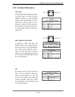
NIC3/NIC4 LED Headers
A LAN3 (NIC3) LED and LAN4 (NIC4)
LED header is located at JPK1. Con-
nect the appropriate cables here to
provide LAN3 and LAN4 LED indica-
tions on your motherboard.
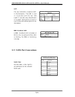
UIO Power Connector
A Universal I/O (UIO) power connec-
tor is located next to the UID button.
Connect this connector to the power
supply to provide adequate power to
the UIO device installed on the slot for
this device to function properly.
Universal I/O Power
Pin Defi nitions
Pins# Defi nition Pin # Defi nition
B1
+5V
A1
+3.3V
B2
+5V
A2
+3.3V
B3
+5V
A3
+3.3V
B4
+5V
A4
+3.3V
B5
+5V
A5
+3.3V
B6
+5V
A6
+3.3V
B7
+5V
A7
+3.3V
B8
+5V
A8
+3.3V
B9
+5V
A9
+3.3V
B10
+5V
A10
+3.3V
B11
-12V
A11
+3.3V
Key
Key
B12
+3.3VSb
A12
+3.3V
B13
+3.3VSb
A13
+12V
B14
GND
A14
+12V
B15
GND
A15
+12V
B16
GND
A16
+12V
B17
GND
A17
+12V
B18
GND
A 18
GND
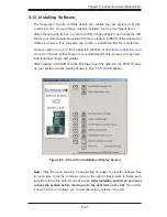
Wake-On-Ring
The Wake-On-Ring header is desig-
nated JWOR1. This function allows
your computer to receive and be
"awakened" by an incoming call when
in the suspend state. See the table on
the right for pin defi nitions. You must
also have a WOR card and cable to
use this feature.
Wake-On-Ring
Pin Defi nitions
Pin# Defi nition
1
Ground (Black)
2
Wake-up
Summary of Contents for SUPERSERVER 6016T-NTRF4+
Page 1: ...SUPERSERVER 6016T URF4 6016T NTRF4 SUPER USER S MANUAL 1 0a ...
Page 5: ...v Preface Notes ...
Page 21: ...Chapter 2 Server Installation 2 7 Figure 2 3 Installing the Server into a Rack ...
Page 23: ...Chapter 2 Server Installation 2 9 Figure 2 4 Accessing the Inside of the System ...
Page 28: ...3 4 SUPERSERVER 6016T URF4 6016T NTRF4 User s Manual Notes ...
Page 48: ...4 20 SUPERSERVER 6016T URF4 6016T NTRF4 User s Manual Notes ...
Page 87: ...Chapter 6 Advanced Chassis Setup 6 9 Figure 6 5 Removing Replacing the Power Supply ...
Page 88: ...6 10 SUPERSERVER 6016T URF4 6016T NTRF4 User s Manual Notes ...
Page 116: ...7 28 SUPERSERVER 6016T URF4 6016T NTRF4 User s Manual Notes ...
Page 118: ...A 2 SUPERSERVER 6016T URF4 6016T NTRF4 User s Manual Notes ...


