background image

Chapter 7: BIOS

7-13

BIOS

Event Log Configuration

Event Logging

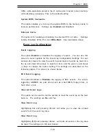
This option Enables or Disables the logging of events.  You can use this

screen to select options for the Event Log Configuration Settings. You can

access sub screens to view the event log and mark all events as read. Use

the up and down arrow keys to select an item, and the plus (+) and minus

(-) keys to change the option setting. The settings are described on the

following pages. The screen is shown below.

ECC Event Logging

This option Enables or Disables the logging of ECC events.  The events

logged by AMIBIOS are post errors such as a bad BIOS, floppy errors, or

hard drive errors.

Clear All Event Logs

This option can be used to tell the system to clear the event log on the next

boot up.  The settings are No and Yes.

View Event Log

Highlighting this and pressing <Enter> will allow you to view the unread

events from the event log area.

View Event Log

Highlighting [OK] and pressing <Enter>  will mark all events in the log area

as read. The settings are OK and Cancel.

CPUs, write operations stored in the L1 cache aren’t copied to main memory

until absolutely necessary. This is the default setting.

System BIOS Cacheable

This option enables you to move the system BIOS to the memory cache to

improve performance.  Settings are Enabled and Disabled.

External Cache

This option is for enabling or disabling  the internal CPU L2 cache.    Settings

include Disabled, Write-Thru and Write-Back.  See description above.

Summary of Contents for SUPERSERVER 6021F

Page 1: ...SUPERSERVER 6021F USER SMANUAL 1 0a SUPER...

Page 2: ...R INABILITY TO USE THIS PRODUCT OR DOCUMENTATION EVEN IF ADVISED OF THE POSSIBILITY OF SUCH DAMAGES IN PARTICULAR THE VENDOR SHALL NOT HAVE LIABILITY FOR ANY HARDWARE SOFTWARE OR DATA STORED OR USED W...

Page 3: ...Manual Organization Chapter 1 Introduction The first chapter provides a checklist of the main components included with the server system and describes the main features of the SUPER P3TDE6 mainboard a...

Page 4: ...r when adding or removing proces sors or main memory and when reconfiguring the motherboard Chapter 6 Advanced Chassis Setup Refer to Chapter 6 for detailed information on the SC822 2U rackmount serve...

Page 5: ...Overvie w C on trol P an el B utto ns C on trol P an el L E Ds SC S I L E Ds Po we r S upp ly S witch M other bo ar d L ED Static Sa fety M B In stalla tio n Ca bles I O P or ts CP U In stalla tio n...

Page 6: ...aring for Setup 2 1 Choosing a Setup Location 2 2 Rack Precautions 2 2 Server Precautions 2 2 2 4 Installing the SuperServer 6021F into a Rack 2 3 Identifying the Sections of the Rack Rails 2 3 Instal...

Page 7: ...wer Cables 5 3 Connecting the Control Panel 5 4 5 4 I O Ports 5 5 5 5 Installing Processors 5 5 5 6 Installing Memory 5 8 5 7 Adding PCI Cards 5 9 SUPER P3TDE6 Layout 5 11 SUPER P3TDE6 Quick Reference...

Page 8: ...ns 5 22 Parallel Port Connector 5 22 Floppy Connector 5 23 IDE Connectors 5 23 Ultra160 SCSI Connectors 5 24 5 12 Installing Software Dirvers 5 25 Chapter 6 Advanced Chassis Setup 6 1 Static Sensitive...

Page 9: ...y 7 25 Hard Disk Drives 7 26 Removable Devices 7 26 ATAPI CD ROM Drives 7 26 7 9 Security Setup 7 27 Supervisor Password 7 27 User Password 7 27 Change Supervisor Password 7 28 Change User Password 7...

Page 10: ...NOTES SUPERSERVER 6021F User s Manual x...

Page 11: ...e with the SuperServer 6021F www supermicro com In addition to the mainboard and chassis various hardware components may have been included with your SuperServer 6021F as listed below l Up to two 2 37...

Page 12: ...CA backplane that provides power bus termination and configuration settings The SCSI drives are also hot swap units Control Panel The SC822 s control panel provides important system monitoring and con...

Page 13: ...e SC822 chassis has an innovative cooling design that includes four 8 cm redundant system cooling intake fan The fans plug into chassis fan connectors that located behind the HDD drive bays and operat...

Page 14: ...ds The South Bridge provides various integrated functions including the PCI to ISA bridge and support for UDMA33 security passwords and system pro tection Plug Play USBs power management interrupt con...

Page 15: ...rive controller and two onboard IDE controllers support one up to four hard drives or ATAPI devices Onboard I O ports includeone COM port two USB ports PS 2 mouse and keyboard ports a video monitor po...

Page 16: ...uropean Office Address Super Micro Computer B V Het Sterrenbeeld 28 5215 ML s Hertogenbosch The Netherlands Tel 31 0 73 6400390 Fax 31 0 73 6416525 E mail sales supermicro nl General Information suppo...

Page 17: ...if it was damaged in any way If the server itself shows damage you should file a damage claim with the carrier who delivered it Decide on a suitable location for the rack unit that will hold the Super...

Page 18: ...tending a component from the rack You should extend only one component at a time extending two or more simultaneously may cause the rack to become unstable Server Precautions Review the electrical and...

Page 19: ...k Rails You should have received two rack rail assemblies with the SuperServer 6021F Each of these assemblies consist of three sections an inner fixed chassis rail that secures to the 6021F A and an o...

Page 20: ...cking Tabs As you have seen both chassis rails have a locking tab which serves two functions The first is to lock the server into place when installed and pushed fully into the rack which is its norma...

Page 21: ...the front of the rack rails Slide the chassis rails into the rack rails keeping the pressure even on both sides you may have to depress the locking tabs when inserting See Figure 2 3 When the server h...

Page 22: ...ou are installing the SuperServer 6021F into a Telco type rack follow the directions given on the previous pages for rack installation The only difference in the installation procedure will be the pos...

Page 23: ...processors already installed into the system board Each processor should have its own heatsink attached See Section 5 5 for instructions on processor installation 3 Verify the proper CPU core bus rat...

Page 24: ...ERVER 6021F Manual Figure 2 5 Accessing the Inside of the SuperServer 6021F with one SCSI Drive removed Figure 2 6 Removing the 5 25 drive bay rails and installing them on the new component CD ROM as...

Page 25: ...ll need to remove the top chassis cover The SCSI disk drives can be installed and removed from the front of the chassis without removing the top chassis cover The 5 25 drive bay cover can be removed b...

Page 26: ...that all power and data cables have been routed in such a way that they do not block the airflow generated by the fans 6 Supplying power to the system The last thing you must do is to provide input p...

Page 27: ...supply This chapter explains the meanings of all LED indicators and the appropriate response you may need to take 3 2 Control Panel Buttons There are two push button buttons located on the front of t...

Page 28: ...cables obstructing the airflow in the system or the ambient room temperature being too warm You should also check to make sure that the chassis cover is installed and that all fans are present and op...

Page 29: ...to blink on and off when that particular drive is being accessed l Red A SAF TE compliant backplane is needed to activate the red LED to indicate a drive failure A SAF TE compliant SCSI backplane is o...

Page 30: ...SUPERSERVER 6021F Manual 3 4 NOTES...

Page 31: ...ing power you should first power down the system with the operating system first and then unplug the power cords of all the power supply units in the system l When working around exposed electrical ci...

Page 32: ...and unbuttoned shirt sleeves which can come into contact with electrical circuits or be pulled into a cooling fan l Remove any jewelry or metal objects from your body which are excellent metal conduc...

Page 33: ...omponents and printed circuit boards PCBs in their antistatic bags until ready for use l Touch a grounded metal object before removing the board from the antistatic bag l Do not let components or PCBs...

Page 34: ...Operating Precautions Care must be taken to assure that the chassis cover is in place when the 6021F is operating to assure proper cooling Out of warranty damage to the 6021F system can occur if this...

Page 35: ...tronic components To prevent damage to any printed circuit boards PCBs it is important to handle them very carefully see previous chapter Also note that the size and weight of the motherboard can caus...

Page 36: ...led in a rack you must first release the retention screws that secure the unit to the rack Then grasp the two handles on either side and pull the unit straight out until the rails lock into place 2 Ch...

Page 37: ...you should take care to keep them routed as they were originally after reconnecting them make sure the red wires connect to the pin 1 locations The following data cables with their locations noted sho...

Page 38: ...ects to the Control Panel printed circuit board located just behind the system status LEDs in the chassis The control signals are all on the even numbered pins See pages 5 13 to 5 15 for details and p...

Page 39: ...mponents 1 Installing the FCPGA processors The P3TDE6 has two 370 pin sockets which support single or dual Intel Pentium III FCPGA 500 MHz 1 26 GHz processors and single or dual low power Pentium III...

Page 40: ...ble thermal compound to best conduct the heat from the processor to the heat sink Make sure that you apply the compound evenly and that good contact is made between the CPU chip the die and the heat s...

Page 41: ...Chapter 5 Installation 5 7 Installation Figure 5 4 Heat Sink Installation...

Page 42: ...both slots of Bank1 if needed 2 Insert each DIMM module vertically into its slot Pay attention to the two notches along the bottom of the module to prevent inserting the DIMM module incorrectly 3 Gent...

Page 43: ...ur thumbs evenly on both sides of the card Finish by using a screw to secure the top of the card shield to the chassis The I O shield protects the motherboard and its components from EMI electromagnet...

Page 44: ...anual Installation Standard PCI and Low Profile PCI Expansion Card Low Profile PCI Expansion Card Standard PCI Expansion Card Figure 5 6a Low Profile versus Standard PCI Card Form Factor Figure 5 6b L...

Page 45: ...J18 CPU CPU2 FAN BANK0 PWR_SEC IDE 1 IDE 2 JP1 J13 J14 ULTRA160 LVD SCSI CHA JF1 JP3 WOR CPU JP62 3V PCI64 2 BIOS 1 SOUTH JP54 JP57 JA4 SLED AIC 7899 SUPER BANK1 BANK0 BANK1 CH FAN1 CPU CH FAN1 SW1 NO...

Page 46: ...ct Open OH Disabled JP64 Watch Dog Open Disabled DIP Switch Description SW1 1 4 CPU Core Bus Ratio Connectors Description ATX POWER 1 Primary ATX Power Connector ATX POWER 2 Secondary ATX Power Connec...

Page 47: ...s located on JF1 Attach the IDE hard drive LED cable to the cor rect pins to display disk activity See Table 5 3 for pin definitions T able 5 1 AT X Pow er Supply Connector Pin D efinitions For 370DE6...

Page 48: ...s to the hardware reset switch on the computer case See Table 5 6 for pin definitions NIC_LED The Network Interface Controller LED connection is located on JF1 Attach the NIC LED cable to these pins t...

Page 49: ...fer to Table 5 10 for pin defini tions Extra Universal Serial Bus Connection USB3 Refer to Table 5 11 for pin defini tions An additional connection for USB3 is included on pins 25 27 29 and 31 of JF1...

Page 50: ...Table 5 14 for pin defini tions Speaker The speaker connection is located on pins 28 30 32 and 34 of JF1 See Table 5 12 for pin definitions T able 5 12 Speaker Connector Pin Definitions JF1 Pin Numbe...

Page 51: ...er is des ignated as WOL Refer to Table 5 17 for pin definitions You must enable the LAN Wake Up setting in BIOS to use this feature You must also have a LAN card with a Wake on LAN connector and cabl...

Page 52: ...is feature is only available when using Supermicro power supplies See Table 5 18 for pin definitions SLED1 SCSI LED Indicator The SLED connector is used to provide an LED indication of SCSI activity R...

Page 53: ...the P3TDE6 SW1 has four individual switches which are used to set the core bus ratio The example on the right will show you which CPU Core Bus Ratio to use The general rule is to divide the CPU speed...

Page 54: ...on before powering up the system again Do not use the PW_ON connector to clear CMOS Position 1 2 Position 2 3 Normal CMOS Clear Front Side Bus Speed CPU speed FSB x Core Bus ratio Core Bus Ratio setti...

Page 55: ...em will notify you in the event of a power supply failure This feature assumes that three power supply units are installed in the chassis with one acting as a backup If you only have one or two power...

Page 56: ...sk drives The connector with twisted wires always connects to drive A and the connector that does not have twisted wires always connects to drive B Parallel Port Connector The parallel port is located...

Page 57: ...IR 20 STEP 22 W rite Data 24 W rite Gate 26 Track 00 28 W rite Protect 30 Read Data 32 Side 1 Select 34 Diskette T able 5 28 Floppy Connector Pin Definitions JP15 Pin Number Function 1 Reset IDE 3 Hos...

Page 58: ...SEL C D REQ I O DB 8 DB 9 DB 10 DB 11 Connector Contact Number 1 2 3 4 5 6 7 8 9 10 11 12 13 14 15 16 17 18 19 20 21 22 23 24 25 26 27 28 29 30 31 32 33 34 Signal Names DB 12 DB 13 DB 14 DB 15 DB P1 D...

Page 59: ...isplay shown in Figure 2 5 should appear If this dis play does not appear click on the My Computer icon and then on the icon representing your CDROM drive Finally double click on the S Setup icon Figu...

Page 60: ...5 26 SUPERSERVER 6021F User s Manual Installation NOTES...

Page 61: ...ly The following measures are generally suffi cient to protect your equipment from ESD damage Precautions l Use a grounded wrist strap designed to prevent static discharge l Touch a grounded metal obj...

Page 62: ...lify the connection Connect the cable from JF1 on the motherboard to JP4 on the Control Panel PCB printed circuit board Make sure the red wire plugs into pin 1 on both JF1 and JP4 Pull all excess cabl...

Page 63: ...n to its fan header on the P3TDE6 motherboard Replacing System Cooling Fans 1 Removing a fan Remove the chassis cover Press the tabs on the top of the fan housing and remove the fan and its housing Th...

Page 64: ...drives Proceed to the next step for instructions Note You must use standard 1 high 80 pin SCA SCSI drives in the SuperServer 6021F CD ROM Floppy Disk Drive For installing removing the CD ROM or floppy...

Page 65: ...stall a drive into the carrier with the printed circuit board side toward the carrier so that the mounting holes align with those in the carrier Secure the drive to the carrier with four screws as sho...

Page 66: ...l The SCSI drive is a hot swap unit meaning that it can be installed and removed while the system is running To remove a SCSI drive first push the release button located beside the drive s LEDs then s...

Page 67: ...slim line CD ROM drive in a 6021F server First release the retention screws that secure the server unit to the rack Grasp the two handles on either side and pull the unit straight out until it locks y...

Page 68: ...the chassis near the fron and push the chassis top rearward about one inch To remove the failed power unit unplug the power cord that connects to the power supply Then remove all screws that connect t...

Page 69: ...Chapter 6 Advanced Chassis Setup 6 9 Figure 6 6 Chassis Rear View Power Supply I O Shield...

Page 70: ...6 10 SUPERSERVER 6021F Manual NOTES...

Page 71: ...he BIOS ROM enabling it to retain the system parameters Each time the computer is powered on the computer is then configured with the values stored in the BIOS ROM by the system BIOS which gains contr...

Page 72: ...drive AMIBIOS supports PC Health Monitoring chips When a failure occurs in a monitored activity AMIBIOS can sound an alarm and display a message The PC Health Monitoring chips monitor CPU temperature...

Page 73: ...illustrate how to navigate through the menus Note Items displayed in gray are preset and cannot be selected Items with a blue arrow are commands not options i e Discard Changes The Main BIOS Setup Men...

Page 74: ...en such as SuperIO Configuration to go to the sub screen for that item Advanced BIOS Setup options are displayed by highlighting the option using the arrow keys All Advanced BIOS Setup options are des...

Page 75: ...dress This option specifies the base I O port address of serial port 2 The settings for this item include Disabled 2F8 3E8 and 2E8 Serial Port 2 IRQ This option specifies the Interrupt Request address...

Page 76: ...for this item include Normal Bi directional EPP and ECP ECP Mode DMA Channel This option allows the user to set the setting for the ECP Mode of the DMA Channel The settings for this item include 0 1 a...

Page 77: ...a method of addressing data on a disk drive In LBA mode the maximum drive capac ity is 137 GB The settings are Disabled and Auto Select Disabled to disable LBA mode Select Auto to enable LBA mode if y...

Page 78: ...lti word DMA0 through DMA2 Select UDMA0 trhough UDMA4 to set Ultra DMA0 through Ultra DMA4 S M A R T S M A R T stands for Self Monitoring Analysis and Reporting Technology a feature that can help pred...

Page 79: ...ed or Disabled Enabled allows the drive to be used normally read write and erase functions can all be performed Disabled prevents the hard disk from being erased This function is effective only when t...

Page 80: ...3 1 2 The Enabled setting is effective only if the device is accessed through BIOS Floppy Drive Seek Use this option to Enable or Disable the floppy seek routine on bootup Boot Settings Configuration...

Page 81: ...er repeats a key to over 20 times per second Under normal opera tions this setting should not be changed Slow This sets the rate the computer repeats a key to under 8 times per second System Keyboard...

Page 82: ...option allows the operating system and applications to be able to read the CPU serial number from your CPUs The settings are Enabled and Dis abled Note This option is not available for Intel Celeron...

Page 83: ...rive errors Clear All Event Logs This option can be used to tell the system to clear the event log on the next boot up The settings are No and Yes View Event Log Highlighting this and pressing Enter w...

Page 84: ...allows the system to auto detect and display the temperatures of CPU1 and CPU2 System Overheat Warning This option allows you to Enable or Disable a system overheat warning signal used to notify you i...

Page 85: ...g at the above address are copied shadowed from ROM to RAM for faster application When set to Cached WP the contents of 16 KB of BIOS SETUP UTILITY Main Advanced Chipset PCIPnP Power Boot Security Exi...

Page 86: ...ncy This option defines the SDRAM CAS Lantency settings CAS stands for Column Address Strobe Settings include CAS Lantgency 3 CAS Lantgency 2 Memory Auto Precharge The settings are Enabled and Disable...

Page 87: ...Full Delay 1 5 BCLK 2 5 BLCK and 3 5 BLCK Scrubbing Enable The settings are Enabled and Disabled AGP Device Address Space Size This settings for this option are 32MB 64MB 128MB 256MB and 512MB AGP Ope...

Page 88: ...ation Data Choosing the Yes setting will cause the PnP configuration data in the BIOS to be cleared on the next boot up Choosing the No setting does not force PnP data to be cleared on the next boot B...

Page 89: ...k with your adapter card manuals first before modifying the default settings in the BIOS PCI IDE BusMaster The settings for this option are Disabled and Enabled Enable to specify that the IDE controll...

Page 90: ...S The Auto setting auto detects USB keyboards or mice and if found allows them to be utilized during boot and while using DOS IRQ 3 IRQ 4 IRQ 5 IRQ 7 IRQ 9 IRQ 10 IRQ 11 IRQ 14 IRQ 15 The settings for...

Page 91: ...ailable means the specified DMA channel is avail able for use by PCI PnP devices Reserved means the specified DMA chan nel is reserved for use by Legacy ISA devices Reserved Memory Size This option sp...

Page 92: ...O S Power Management Power Button Mode Sleep Button Mode Green PC Monitor Power State Video Power Down Mode Inactivity Timer Suspend Timeout Minutes IRQ1 IRQ3 IRQ4 IRQ5 IRQ6 IRQ7 IRQ9 IRQ10 IRQ11 IRQ1...

Page 93: ...S This option allows the system to utilize Intel s ACPI Advanced Configuration and Power Interface specification Settings are No and Yes DOS Windows 3 x and Windows NT are examples of non ACPI aware o...

Page 94: ...me the system s normal power up state when activated Settings are Ignore and Monitor All IRQs are defaulted to Ignore except for IRQ 1 12 and 14 whcih default to Monitor USB Controller Resume This all...

Page 95: ...able system devices The settings for the 1st Boot Device are Removable Device ATAPI CDROM Hard Drive and Disabled 2nd Boot Device The settings for the 2nd Boot Device are Removable Device ATAPI CDROM...

Page 96: ...e boot sequence of hard drives that have been auto detected or entered manually on your system Removable Devices Use this screen to view the boot sequency of the removeable devices that have been auto...

Page 97: ...y If you select password support you are prompted for a 1 6 character password Type the password on the keyboard The password does not appear on the screen when typed Make sure you write it down If yo...

Page 98: ...rd Use this option to clear the user password so that it is not required to be entered when the system boots Boot Sector Virus Protection This option allows you to enable or disable a virus detection...

Page 99: ...p with saving the changes Select Screen Select Item Enter Go to Sub Screen F1 General Help F10 Save and Exit ESC Exit V02 03 C Copyright 1985 2000 American Megatrends Inc Exit Saving Changes Highlight...

Page 100: ...vices and system features Load Failsafe Defaults Highlighting this setting and then pressing Enter provides the safest set of parameters for the system Use them if the system is behaving errati cally...

Page 101: ...screen Fatal errors are those which will not allow the system to continue the boot up procedure If a fatal error occurs you should consult with your system manufacturer for possible repairs These fat...

Page 102: ...BIOS cannot switch to protected mode 7 beeps Processor exception interrupt error The CPU generated an exception interrupt 8 beeps Display memory read write error The system video adapter is either mis...

Page 103: ...starting Next the initialization code checksum will be verified D1h Initializing the DMA controller performing the keyboard controller BAT test starting memory refresh and entering 4 GB flat mode nex...

Page 104: ...ROM FFh Flash ROM programming was successful Next restarting the system BIOS B 3 Uncompressed Initialization Codes The following runtime checkpoint codes are listed in order of execution These codes...

Page 105: ...ng the 15 second on off time next 2Bh Passing control to the video ROM to perform any required configuration before the video ROM test 2Ch All necessary processing before passing control to the video...

Page 106: ...mode is set Displaying the power on message next 38h Initializing the bus input IPL general devices next if present See the last page of this chapter for additional information 39h Displaying bus ini...

Page 107: ...rforming the sequential and random memory test next 50h The memory below 1 MB has been tested and initialized Adjusting the displayed memory size for relocation and shadowing next 51h The memory size...

Page 108: ...keyboard reset error or stuck key was found Issuing the keyboard controller interface test command next 82h The keyboard controller interface test completed Writing the command byte and initializing t...

Page 109: ...roller next 91h The floppy drive controller has been configured Configuring the hard disk drive controller next 95h Initializing the bus option ROMs from C800 next See the last page of this chapter fo...

Page 110: ...d typematic rate is set Programming the memory wait states next A5h Memory wait state programming is over Clearing the screen and enabling parity and the NMI next A7h NMI and parity enabled Performing...

Page 111: ...ow byte of checkpoint is the system BIOS checkpoint where control is passed to the different bus routines The high byte of checkpoint indicates that the routine is being executed in Different buses Hi...

Page 112: ...SUPERSERVER 6021F User s Manual B 10 APPENDIX B NOTES...

Page 113: ...ght BIOS 4 Mb AMI Flash ROM APM 1 2 DMI 2 1 PCI 2 2 ACPI 1 0 Plug and Play PnP Memory Capacity Four 168 pin DIMM sockets supporting up to 4 GB registered ECC SDRAM Note 1 The memory speed must match t...

Page 114: ...MHzPCI slots One 2x AGP Pro slot PC Health Monitoring Seven onboard voltage monitors for CPU core chipset voltage 5V and 12V Fan status monitor with firmware software on off control Environmental tem...

Page 115: ...s Supported Windows NT Windows 2000 Solaris Netware SCO UNIX and Linux Dimensions 16 7 x 3 46 x 25 6 in 425 x 88 x 650 mm W x H x D Weight Net Bare Bone 32 lbs 14 5 kg Gross Bare Bone 54 lbs 24 5 kg R...

Page 116: ...SUPERSERVER 6021F User s Manual C 4 Notes...

Reviews: