58
Chapter 3: Maintenance and Component Installation
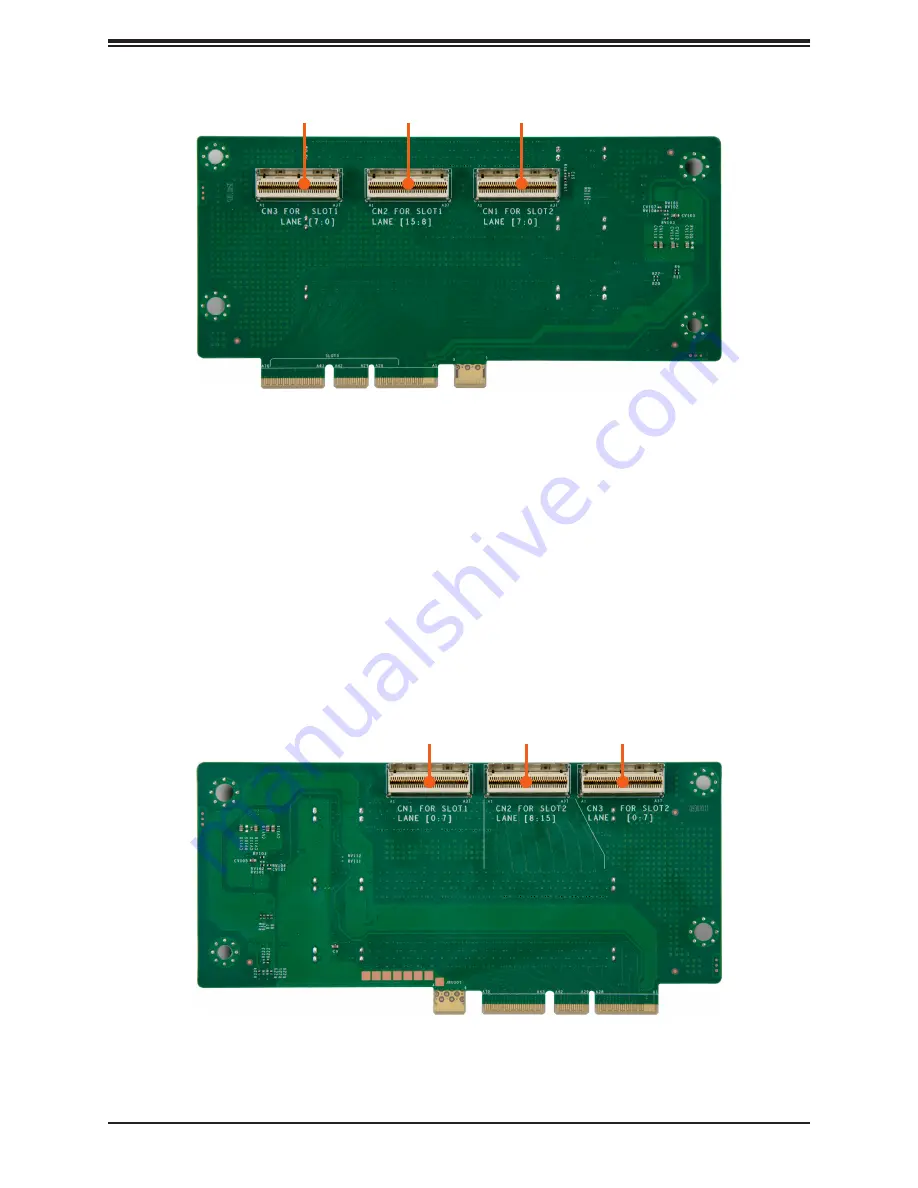
Figure 3-19. Rear View of Riser Card RSC-D2R-668G4
The same relationships apply for slots 4 and 5, and headers P2-PCIE0 and P2-PCIE1.
Slots 4 and 5 on riser card on RSC-D2R-668G4 (see picture below) can be connected for
use in several ways using motherboard headers P2-PCIE0 and P2-PCIE1.
•
To enable slot 5 as x16, both headers are connected to the riser card at CN2 and CN3.
This applies for a GPU using slot 5. Slot 4 is disabled. (More details on GPU in section 6.1).
•
To enable slot 4 as x8 and slot 5 as x8, headers are connected to CN1 and CN3.
•
If P2-PCIE0 or P2-PCIE1 are used for NVMe storage connections, that header cannot be
used for riser card connections, and slots 4 and 5 are unavailable.
Figure 3-18. Rear View of Riser Card RSC-D2-668G4
CN3
CN2
CN1
CN1
CN2
CN3


