16
SuperServer 7089P-TR4T User's Manual
Major Components on the X11OPi Board
J6 J4
J2
JPWR4
J3
Guide PWR1 PWR2
Guide
JPWR5
JPWR3
NVME0
NVME1
NVME2
NVME3
CPU Slot2
PCI-E 3.0 x 16
CPU Slot1
PCI-E 3.0 x 16
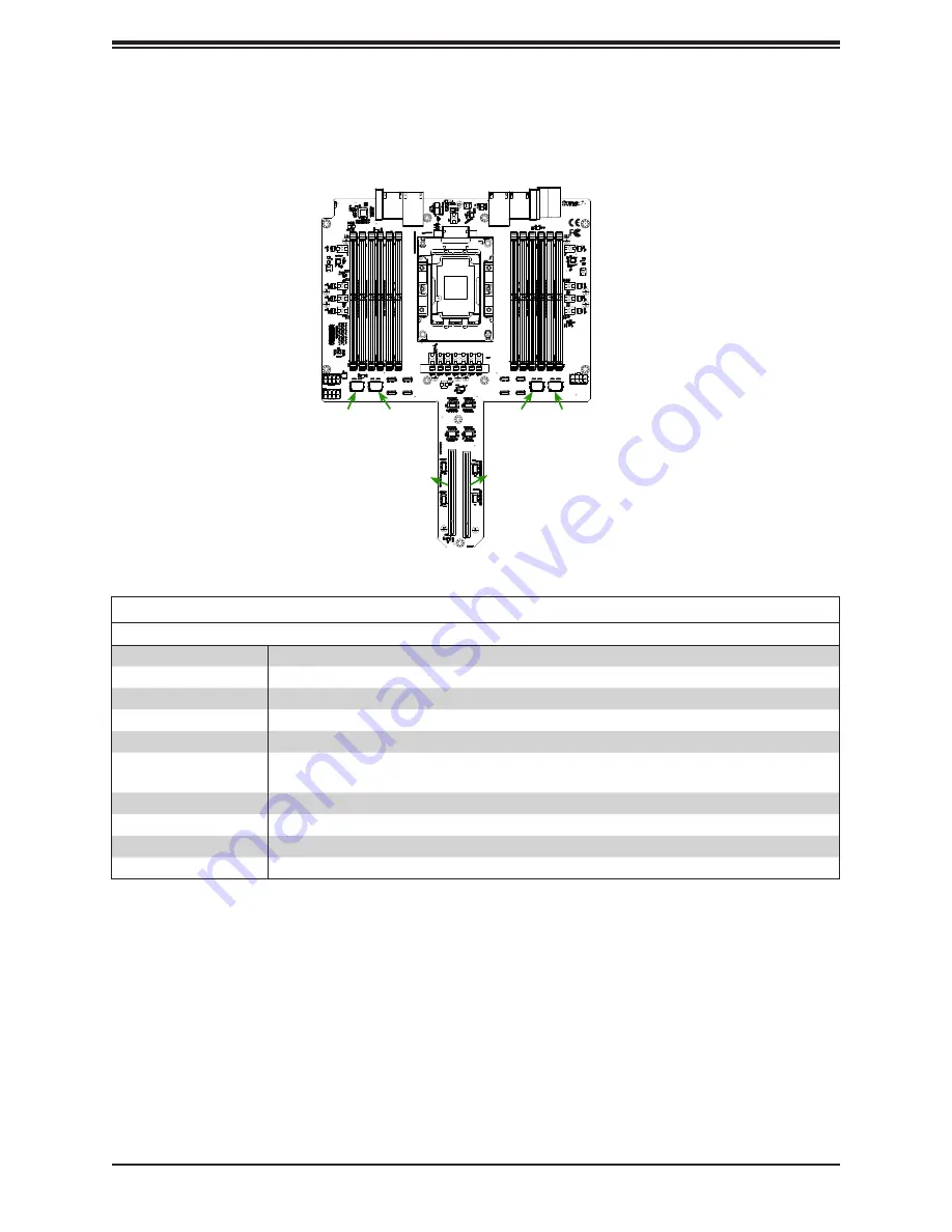
Figure 1-8. CPU Board Major Components
Connectors on the X11OPi
Connector
Description
J3/J6
High speed interconnect
J2/J4
High speed interconnect
J7
PCI-E 3.0 x16 slot supported by the CPU (Slot1)
J8
PCI-E 3.0 x16 slot supported by the CPU (Slot2)
J9/J10
CPU card guides (to be used to attach the CPU cards to the midplane board)
JLED1
This array of LEDs is provided to indicate a memory slot on the CPU board that has failed. If
illuminated red, the designations (A1, A2, etc.) correspond to the failed slot on the CPU board.
JPWR3/JPWR4/JPWR5
GPU power connectors 3/4/5
PWR1/PWR2
12-pin CPU power connectors 1/2
NVME0-NVME3
Non-Volatile Memory Express (NVME) connectors 1/2/3/4
DIMMA1-F2
DIMM memory modules (DIMMA1/A2/B1/B2/C1/C2/D1/D2/E1/E2/F1/F2)
Notes:
Note1:
See Chapter 4 for detailed information on jumpers, I/O ports, and JF1 front panel
connections.
Note 2:
Components/jumpers/LED indicators not documented are reserved for internal testing
only.


