10
SuperServer E200-9B User's Manual
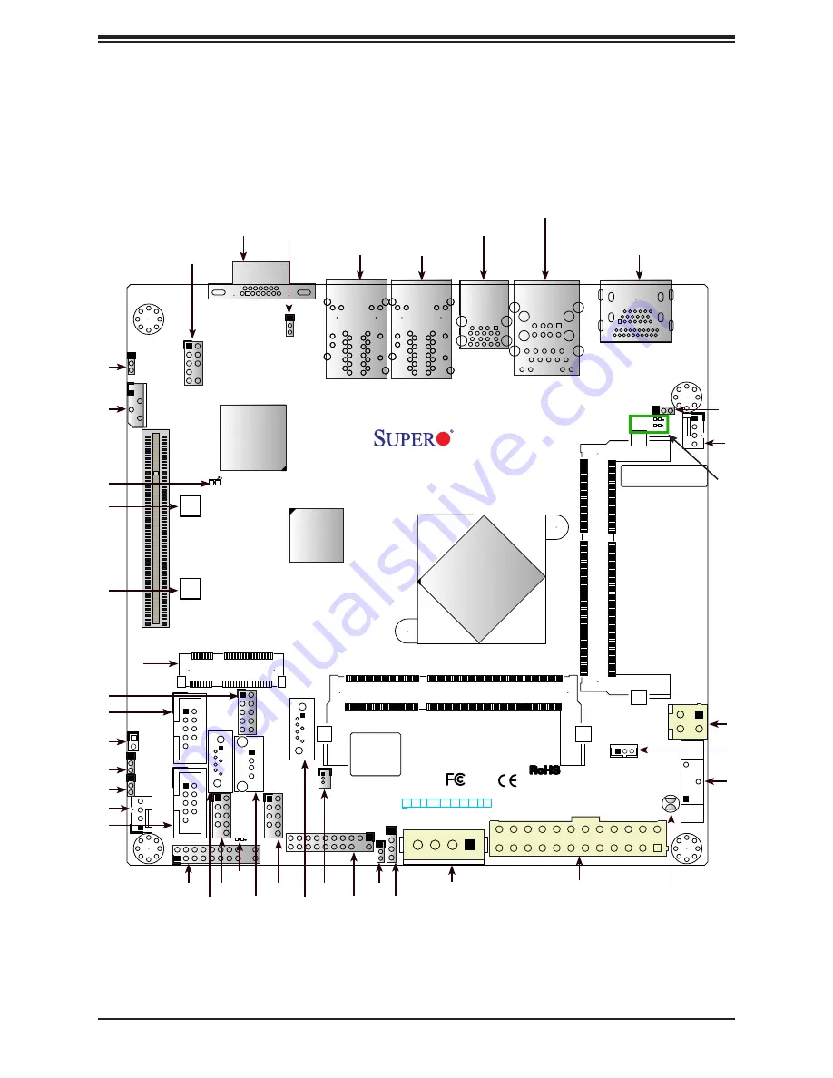
1.5 Motherboard Layout
Below is a layout of the X11SBA-LN4F with jumper, connector and LED locations shown. See
the table on the following page for descriptions. For detailed descriptions, pinout information
and jumper settings, refer to Chapter 4.
Figure 1-2. Motherboard Layout
BIOS LICENSE
BAR CODE
X11SBA
DESIGNED IN USA
JD2
JIPMB1
JPG1
LEDBMC
JPW1
JTPM1
I-SA
TA0
I-SATA1
COM2
COM1
JSATA1
JPW2
FAN2
JI2C1
JI2C2
JPAC1
JPME2
JSD1
BT1
LED3
JGP1
JBT1
JF1
SRW1
SRW2
JWD1
JSTBY1
LED1
LED2
mSATA/mini PCIE
SODIMM2(1.35V only)
SODIMM1(1.35V only)
(install first)
HDMI/DP
USB7/8
USB5/6
USB4
AUDIO FP
USB2/3(3.0)
CPU
IPMI_LAN
LAN3
LAN1
LAN4
LAN2
VGA
RST
PWR
ON
JF1
CPU SLOT1 PCI-E 2.0 X1 (IN X8)
X OH/FF NIC
1
NIC
2
PWR
LED
LED
HDD
NMI
X
USB0/1
FAN1
1
JL1
HDMI/DP
USB2/3 (3.0)
USB0/1 IPMI_LAN
LAN1/3
LAN2/4
VGA
JPG1
AUDIO FP
JPAC1
JIPMB1
LEDBMC
SRW1
SRW2
COM1
JL1
JI2C2
JI2C1
COM2
FAN2
mSATA/mini
PCIE
JF1 USB5/6 USB7/8
USB4
JGP1
I-SATA0
I-SATA1
JSD1
JTPM1
JWD1
JD2
JSATA1
JPW1
JBT1
FAN1
JPME2
LED1/
LED2
BT1
JPW2
JSTBY1
LED3


