47
Chapter 3: Maintenance and Component Installation
Heatsink (Reverse Side)
d
a
b
c
A
, B, C, D: Peek Nut
1, 2, 3, 4: Rotating Wire
a, b, c, d: Threaded Fastener
Peek Nut
(Unlatched)
(latched)
Rotating Wire
3
Peek Nut
A
B
C
D
Rotating Wire
1
2
Rotating Wire
Rotating Wire
4
Threaded Fastener
CPU Socket
Peak Nut
Rotating Wire
Side View
Top View
Unlatched State
a
b
c
d
(a, b, c, d: Threaded Fasteners)
CPU Socket Pin1
Threaded Fastener
CPU Socket
Preparing to Install the Processor Heatsink Module (PHM) into
the CPU Socket
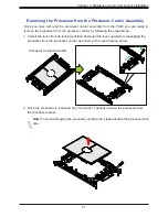
After assembling the Processor Heatsink Module (PHM), you are ready to install it into the
CPU socket. To ensure the proper installation, please follow the procedures below:
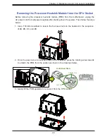
1. Locate four threaded fasteners (a, b, c, d) on the CPU socket.
2. Locate four peek nuts (A, B. C. D) and four rotating wires (1, 2, 3, 4) on the heatsink as
shown in the graphics below.
3. Check the rotating wires (1, 2, 3, 4) to make sure that they are at unlatched positions as
shown in the drawing below before installing the PHM into the CPU socket.


