background image

77

Chapter 4: Motherboard Connections

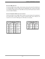
NCSI Connector

The NCSI connector (JNCSI1) is used to connect a Network Interface Card (NIC) to the 
motherboard which allows the onboard BMC (Baseboard Management Controller) to 
communicate with a network.

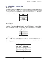
Front Control Panel Header for FFC/FPC Cable

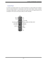
JFP1 contains header pins for various buttons and indicators that are normally located on a 

control panel at the front of the chassis. These connectors are designed specifically for use 
with Supermicro chassis. Refer to the table below for pin definitions of JFP1. Regarding the 

pin functions, refer to Section 2.6. (JFP1 and JF1 have the same pin functions although the 

pin numbers might differ.)

Front Control Panel Header for FFC/FPC Cable

Pin Definitions

Pin#

Definition

20

Ground

19

Power Fail

18

+5V

17

+5V

16

+5V

15

+3.3 Pull Up

14

Ground

13

FP Sensor Clock

12

FP Sensor DATA

11

Ground

10

+3.3VSB

9

FP PWR LED

8

STBY LED

7

HDD LED

6

NIC1 (Link) LED

5

No Connection

4

Blue+(Red OH/Fan Fail/PWR Fail for LED5/Blue UID LED)

3

Red+(Blue LED_Cathode_UID)

2

Reset or UID Button

1

Power Button

Summary of Contents for SuperServer SSG-620P-E1CR24H

Page 1: ...USER S MANUAL Revision 1 0 Storage SuperServer SSG 620P E1CR24H SSG 620P E1CR24L ...

Page 2: ... Class A device or in residential environment for Class B device This equipment generates uses and can radiate radio frequency energy and if not installed and used in accordance with the manufacturer s instruction manual may cause harmful interference with radio communications Operation of this equipment in a residential area is likely to cause harmful interference in which case you will be requir...

Page 3: ...rivers and utilities https www supermicro com wdl Product safety info http www supermicro com about policies safety_information cfm If you have any questions please contact our support team at support supermicro com This manual may be periodically updated without notice Please check the Supermicro website for possible updates to the manual revision level Secure Data Deletion A secure data deletion...

Page 4: ...llation 2 1 Overview 20 2 2 Unpacking the System 20 2 3 Preparing for Setup 20 Choosing a Setup Location 20 Rack Precautions 21 Server Precautions 21 Rack Mounting Considerations 21 Ambient Operating Temperature 21 Airflow 22 Mechanical Loading 22 Circuit Overloading 22 Reliable Ground 22 2 4 Installing the System into a Rack 23 Separating the Sections of the Rack Rails 23 Releasing the Inner Rail...

Page 5: ...ating the Processor Heatsink Module PHM 45 Preparing the CPU Socket for Installation 46 Preparing to Install the Processor Heatsink Module PHM into the CPU Socket 47 Installing the Processor Heatsink Module PHM 48 Removing the Processor Heatsink Module from the CPU Socket 49 Removing the Processor Carrier Assembly from the Processor Heatsink Module PHM 50 Removing the Processor from the Processor ...

Page 6: ...utput Ports 69 4 2 Power Connections 72 4 3 Headers and Connectors 73 Control Panel 78 Front Control Panel LEDs 79 4 4 Jumpers 83 4 5 LED Indicators 85 4 6 Storage Ports 86 Chapter 5 Software 5 1 Microsoft Windows OS Installation 87 5 2 Driver Installation 89 5 3 SuperDoctor 5 90 5 4 BMC 91 BMC ADMIN User Password 91 Chapter 6 Optional Components 6 1 Additional Storage Drives 92 6 2 Storage Contro...

Page 7: ...3 Troubleshooting Procedures 104 General Technique 104 No Power to the System 104 No Video 105 System Boot Failure 105 Memory Errors 105 Losing the System Setup Configuration 105 When the System Becomes Unstable 106 7 4 Crash Dump Using BMC 108 7 5 CMOS Clear 109 7 6 BMC Reset 109 7 7 Where to Get Replacement Components 110 7 8 Reporting an Issue 110 Technical Support Procedures 110 Returning Merc...

Page 8: ...Address Super Micro Computer B V Het Sterrenbeeld 28 5215 ML s Hertogenbosch The Netherlands Tel 31 0 73 6400390 Fax 31 0 73 6416525 Email sales supermicro nl General Information support supermicro nl Technical Support rma supermicro nl Customer Support Website www supermicro nl Asia Pacific Address Super Micro Computer Inc 3F No 150 Jian 1st Rd Zhonghe Dist New Taipei City 235 Taiwan R O C Tel 88...

Page 9: ...e 4 0 x16 AIOM see Section 3 9 for details I O Ports LAN One RJ45 dedicated IPMI LAN port USB Two USB 3 0 ports Rear One VGA port Rear One COM port Rear Two Super DOM Disk on Module ports System Cooling Five heavy duty 8 cm fans with optimal fan speed control Power Two redundant 1600W power supplies 80Plus Titanium level Form Factor 2U WxHxD 17 2 x 3 5 x 34 in 437 x 89 x 864 mm A Quick Reference G...

Page 10: ...e meaning of the status indicator is described in the table below For OS RAID or non RAID configurations some LED indications are not supported such as hot spare For VROC configurations refer to the VROC section in this manual System Features Front Feature Description Control Panel One control panel see Control Panel for details UID Switch LED The unit identification UID button turns on or off the...

Page 11: ...etwork activity on LAN2 when flashing Power Fail LED Indicates a power supply module has failed Information LED Alerts operator to several states as noted in the table below Control Panel Figure 1 2 Control Panel Drive Carrier LED Indicators Color Blinking Pattern Behavior for Device Activity LED Blue Solid On Idle SAS NVMe drive installed Blue Blinking I O activity Off Idle SATA drive installed S...

Page 12: ... solid An overheat condition has occurred Red blinking at 1Hz Fan failure check for an inoperative fan Red blinking at 0 25Hz Power failure check for a non operational power supply Red solid with Power LED blinking green Fault detected Blue and red blinking at 10 Hz Recovery mode Blue solid UID has been activated locally to locate the server in a rack environment Blue blinking at 1Hz UID has been ...

Page 13: ...ng a shutdown failure OCP OVP fan fail OTP UVP Amber blinking Power supply warning events where the power supply continues to operate high temperature over voltage under voltage etc Green blinking AC present only 12V standby ON module off Green solid Output on functioning normally Expansion Card Chassis Slots Item Description 1 AIOM PCIe 4 0 x16 CPU1 2 SLOT2 3 PCIe 4 0 x16 CPU2 3 SLOT1 PCIe 4 0 x1...

Page 14: ...em Architecture This section shows the locations of the system electronic components Figure 1 4 Main Component Locations Storage Backplanes BPN SAS3 826SEL1 N4 Motherboard X12DSC A6 Power Supply Modules DIMM Slots Processors System Fans ...

Page 15: ...pply Dual redundant modules DIMM Slots 16 DIMM memory slots Processors Dual 3rd Gen Intel Xeon Scalable processors with heatsinks SNK P0077V System Fans Five 8 cm fans with Optimal Fan Speed Control FAN 0168L4 Motherboard X12DSC A6 Storage Backplanes Dual BPN SAS3 826SEL1 N4 ...

Page 16: ...ATA1 S SATA0 BT1 BMC S SATA3 S SATA2 BMC_LAN LEDPWR JPWR1 JPV3 JPV2 FAN7 FAN6 FAN5 FAN4 FAN3 P1 AIOM PCI E 4 0 X16 JPV1 FAN2 FAN1 USB2 3 0 S SGPIO1 SATA DOM POWER JIPMB1 JFP1 JUID FP1 RST OR UID P2 SLOT1 PCI E 4 0 X16 P2 SLOT2 PCI E 4 0 X16 JNCSI1 NCSI interface for IPMI shared LAN P2 SLOT3 PCI E 4 0 X16 JNVI2C1 JUIDB1 USB0 1 3 0 VGA COM1 P1_NVME3 P1_NVME2 P1_NVME1 P1_NVME0 JBT1 M 2 HC_1 PCI E 4 0...

Page 17: ...rol Panel Header JFP1 Front Control Panel Header for FFC FPC cable FCC Flexible Flat Cable FPC Flexible Printed Circuit JIPMB1 4 pin BMC external I2 C header JL1 Chassis intrusion header JNCSI1 Network Controller Sideband Interface NC SI connector for BMC shared LAN JNVI2C1 NVMe I2 C header JPI2C1 Power System Management Bus SMBus I2 C header JPV1 JPV2 JPV3 8 pin Power Connectors required JPWR1 24...

Page 18: ... support of SuperDOM devices DOM Disk on Module S SATA2 S SATA3 Intel PCH SATA 3 0 ports with support of RAID 0 1 5 10 S SGPIO1 Serial general purpose I O connection header for S SATA0 1 2 3 SRW1 SRW4 M 2 device mounting holes USB0 USB1 Rear I O USB 3 0 ports USB2 Internal USB 3 0 vertical Type A connector VGA Rear VGA port on the I O back panel ...

Page 19: ...en4 COM 1 CONN DMI3 0 3 VGA CONN PCI E X16 Gen4 FAN 1 7 PCI E X16 Gen4 X12DSC A6 Temp Sensor RT2 CPU 2 RTL8211F PCH C621A SATA x2 Internal sSATA 0 1 SATA 3 sSATA 2 3 SATA DOM x2 Internal SATA 3 Dedicated LAN USB2 4 CPLD NAND Flash LSPI SPI TPM HEADER PCI E X4 Gen4 Debug Card M 2 M key PCIex4 SATA3 SATA 3 BMC USB2 5 CPLD XO3 324 Pin SATA 3 eSPI PCI E X1 SPI M 2 M key PCIex4 SATA3 USB 2 0 X1 PCI E X...

Page 20: ... be situated in a clean dust free area that is well ventilated Avoid areas where heat electrical noise and electromagnetic fields are generated It will also require a grounded AC power outlet nearby Be sure to read the precautions and considerations noted in Appendix A 2 3 Preparing for Setup The box in which the system was shipped should include the rackmount hardware needed to install it into th...

Page 21: ... the electrical and general safety precautions in Appendix A Determine the placement of each component in the rack before you install the rails Install the heaviest server components at the bottom of the rack first and then work your way up Use a regulating uninterruptible power supply UPS to protect the server from power surges and voltage spikes and to keep your system operating in case of a pow...

Page 22: ... be maintained at all times To ensure this the rack itself should be grounded Particular attention should be given to power supply connections other than the direct connections to the branch circuit i e the use of power strips etc To prevent bodily injury when mounting or servicing this unit in a rack you must take special precautions to ensure that the system remains stable The following guidelin...

Page 23: ...es in the rack mounting kit Each assembly consists of three sections An inner rail that secures directly to the chassis an outer rail that secures to the rack and a middle rail that slides in the outer rail These assemblies are specifically designed for the left and right side of the chassis Figure 2 1 Identifying the Inner Rails Middle Rails and Outer Rails Warning Do not pick up the server with ...

Page 24: ...he middle and outer rails before installing the inner rail on the chassis Releasing the Inner Rail from the Middle and Outer Rails 1 Lift the front latch on the inner rail and pull the inner rail out of the middle rail and the middle rail out of the outer rail until the rails are fully extended 2 Press down the locking lever on the inside of the inner rail to release the inner rail Continue to pul...

Page 25: ...ctly identified 2 Place the inner rail firmly against the side of the chassis aligning the pins on the side of the chassis with the slotted thru holes in the inner rail 3 Slide the inner rail toward the rear of the chassis until the pins are at the end of the narrow slot which secures the inner rail to the chassis An optional screw may be added for extra security 4 Repeat for the other inner rail ...

Page 26: ...s into place 4 The outer rail is actually two pieces that slide to lengthen Pull out the rear of the outer rail adjusting the length until the square pin assembly passes then fits against the back of the rear post Be careful to keep the rail level 5 Insert the pins at the rear of the outer rail into the square holes on the rear of the rack Push until the latch snaps into place 6 Repeat for the oth...

Page 27: ...ssis with the front of the middle rails 3 Slide the inner rails on the chassis into the middle rails keeping the pressure even on both sides When partially in the locking levers will stop further progress 4 Press down the locking levers on the inside of the inner rails and push the chassis all the way into the rear of the rack The front latches will click into place The chassis is now mounted in t...

Page 28: ... people to lift it out Removing the Chassis 1 Lift the right and left front latches which are just below the LED control panels on the front edges of the chassis 2 Pull the chassis forward until it clicks to a stop 3 Press down the locking lever on the inside of the inner rail Figure 2 2 to release the server Continue to pull the server out of the middle rails 1 2 1 ...

Page 29: ...ile pushing the plastic release button green in drawing just below it 2 While holding the release button in pull the outer rail forward to disengage the pins and the front of the rail from the rack 3 Support the front of the outer and middle rail assembly while releasing the rear 4 Remove the outer rail from the rear of the rack in the same way as the front Slide the safety slider up and push and ...

Page 30: ...he system is extended out the front of the rack The kit includes six fabric Velcro cable ties The CMA attaches to the rack mounting rails by means of four connectors They are labeled on the connectors 1 2 3 and 4 Installing the Cable Management Arm 1 Slide CMA connector 1 forward onto the two posts on the rear of the right inner rail right side when viewed from the front It snaps into place 2 Slid...

Page 31: ...tor 4 align the metal tabs with the slots on the rear of the left outer rail and push it forward It snaps into place 5 Open the six red plastic caps and route the cables into the wire carrier 6 Use the six Velcro straps to secure the cables to the CMA Use a strap on either side of each joint and one on each connector 7 Slide the chassis forward and backward in the rack to confirm that the cable ma...

Page 32: ...Remove cables from the CMA releasing the Velcro straps and the red plastic caps 2 For CMA connector 4 pull the metal release tab toward the center of the rack and slide the connector toward the rear to release it 3 For CMA connectors 3 2 and 1 depress the front edge of the yellow plastic rocker lock and slide the connector toward the rear to release it ...

Page 33: ...1 Removing Power Use the following procedure to ensure that power has been removed from the system This step is necessary when removing or installing non hot swap components or when replacing a non redundant power supply 1 Use the operating system to power down the system 2 After the system has completely shut down disconnect the AC power cord s from the power strip or outlet If your system has mo...

Page 34: ...can be removed to access the mid chassis drives or fans while the server continues to operate Removing the Mid chassis Cover Remove the two screws securing each side of the cover push in the release buttons then lift the cover Warning Except for short periods of time do not operate the server without the cover in place The chassis cover must be in place to allow for proper airflow and to prevent o...

Page 35: ...re 3 2 Removing the Rear Cover Rear Cover Removing the Rear Cover Remove the two screws on the side of the chassis and the thumbscrew at the rear of the chassis then slide the cover to the rear and off Remove the Screw Remove the Screw Unlock the Thumbscrew ...

Page 36: ...wer supplies after shutting down the system Check that the plastic protective cover is on the CPU socket and none of the socket pins are bent If they are contact your retailer When handling the processor avoid touching or placing direct pressure on the LGA lands gold contacts Improper installation or socket misalignment can cause serious damage to the processor or CPU socket which may require manu...

Page 37: ...37 Chapter 3 Maintenance and Component Installation 1 The 3rd Gen Intel Xeon Scalable Processor Processor Top View 3D Cutout CPU Key Pin 1 CPU Key Pin 1 Processor Top View ...

Page 38: ...38 Chapter 3 Maintenance and Component Installation Carrier Bottom View 2 The Processor Carrier ...

Page 39: ...tallation 3 Heatsink Note Exercise extreme care when handling the heatsink Pay attention to the edges of heatsink fins which can be sharp To avoid damaging the heatsink please do not apply excessive force on the fins when handling the heatsink ...

Page 40: ...40 Chapter 3 Maintenance and Component Installation Plastic Protective Cover Overview of the CPU Socket The CPU socket is protected by a plastic protective cover CPU Socket ...

Page 41: ... Carefully follow the instructions given in the installation section to place a processor into the carrier to create a processor carrier 1 The 3rd Gen Intel Xeon Scalable Processor 2 Processor Carrier 3 Processor Carrier Assembly Intel Processor Bottom View Processor 2D Processor 3D Processor Carrier 3D Processor Carrier 2D Intel Processor Carrier Top View with Processor Seated inside the Carrier ...

Page 42: ...atsink Module The Processor Heatsink Module PHM contains a heatsink a processor carrier and a 3rd Gen Intel Xeon Scalable processor 1 Heatsink with Thermal Grease 2 Processor Carrier 4 Processor Heatsink Module PHM Bottom View 3 The 3rd Gen Intel Xeon Scalable Processor Bottom View ...

Page 43: ... CPU contacts facing down Locate the small gold triangle at the corner of the processor and the corresponding hollowed triangle on the processor carrier as shown in the graphics below Please note that the triangle indicates Pin 1 location Pin 1 Pin 1 2 First turn over the processor carrier and locate Pin 1 on the CPU and Pin 1 on the carrier Then turn the processor over with the processor reverse ...

Page 44: ...rly aligned carefully place one end of the processor into the latch marked 1 on the carrier and place the other end of processor into the latch marked 2 6 After the processor is placed inside the carrier examine the four sides of the processor making sure that the processor is properly seated on the carrier 1 2 A B Latch Latch a CPU Key on the processor CPU Key on the carrier CPU Key on the proces...

Page 45: ...wn in the drawing below 2 Hold the processor carrier assembly top side with thermal grease facing up and locate the triangle on the CPU and the triangle on the carrier Triangle indicates Pin 1 3 Using Pin 1 as a guide turn the processor carrier assembly over with the gold contacts facing up Locate Pin 1 A on the processor and Pin 1 a on the processor carrier assembly a 4 Align the corner marked a ...

Page 46: ...n This motherboard comes with a plastic protective cover installed on the CPU socket Remove it from the socket by following the instructions given in the drawings below Removing the Plastic Protective Cover from the Socket 1 Press the tabs inward 2 Pull up the protective cover from the socket ...

Page 47: ...aded Fastener CPU Socket Preparing to Install the Processor Heatsink Module PHM into the CPU Socket After assembling the Processor Heatsink Module PHM you are ready to install it into the CPU socket To ensure the proper installation please follow the procedures below 1 Locate four threaded fasteners a b c d on the CPU socket 2 Locate four peek nuts A B C D and four rotating wires 1 2 3 4 on the he...

Page 48: ...s on the CPU socket 2 Once they are aligned gently place the heatsink on top the CPU socket making sure that each peek nut is properly attached to its corresponding threaded fastener Latched State Top View 3 Press all four rotating wires outwards and make sure that the heatsink is securely latched unto the CPU socket 4 With a T30 bit screwdriver tighten all peek nuts in the sequence of A B C and D...

Page 49: ...rboard unplug the AC power cord from all power supplies after shutting down the system Then follow the steps below 1 Use a T30 bit screwdriver to loosen the four peek nuts on the heatsink in the sequence of A B C and D 2 Once the peek nuts are loosened from the CPU socket press the rotating wires inwards to unlatch the PHM from the socket as shown in the drawings below 3 Gently lift the PHM upward...

Page 50: ...please follow the steps below 1 Detach four plastic clips marked a b c d on the processor carrier assembly from the four corners of heatsink marked A B C D in the drawings below Pin1 Pin1 A B C D a b c d Processor Carrier Assembly Reverse Side View Heatsink Reverse Side View 2 When all plastic clips are detached from the heatsink remove the processor carrier assembly from the heatsink ...

Page 51: ...sor carrier by following the steps below 1 Unlock the lever from its locking position and push the lever upwards to disengage the processor from the processor carrier as shown in the right drawing below 2 Once the processor is loosened from the carrier carefully remove the processor from the processor carrier Note To avoid damaging the processor and its pins please handle the processor with care L...

Page 52: ...d support depends on the processors used in the system For validated memory use our Product Resources page DDR4 Memory Support for the 3rd Gen Intel Xeon Scalable Processors DDR4 Memory Support for the 3rd Gen Intel Xeon Scalable Processors Type Ranks Per DIMM Data Width DIMM Capacity GB Speed MT s Voltage V Slots Per Channel SPC and DIMMs Per Channel DPC 1DPC 1 DIMM Per Chan nel 2DPC 2 DIMM Per C...

Page 53: ...MC1 P1 DIMMG1 CPU2 P2 DIMMA1 P2 DIMME1 2 CPUs 8 DIMMsNote CPU1 P1 DIMMA1 P1 DIMME1 P1 DIMMC1 P1 DIMMG1 CPU2 P2 DIMMA1 P2 DIMME1 P2 DIMMC1 P2 DIMMG1 2 CPUs 10 DIMMs CPU1 P1 DIMMA1 P1 DIMME1 P1 DIMMC1 P1 DIMMG1 P1 DIMMB1 P1 DIMMF1 CPU2 P2 DIMMA1 P2 DIMME1 P2 DIMMC1 P2 DIMMG1 2 CPUs 12 DIMMsNote CPU1 P1 DIMMA1 P1 DIMME1 P1 DIMMC1 P1 DIMMG1 P1 DIMMB1 P1 DIMMF1 CPU2 P2 DIMMA1 P2 DIMME1 P2 DIMMC1 P2 DIM...

Page 54: ...DIMMG1 P1 DIMMC1 P1 DIMMD1 P1 DIMMA1 P1 DIMMB1 4 4 AD MM One x4 PMem DDR4 PMem DDR4 DDR4 PMem DDR4 PMem One x4 DDR4 PMem DDR4 PMem PMem DDR4 PMem DDR4 6 1 AD One x1 DDR4 DDR4 DDR4 DDR4 PMem DDR4 DDR4 DDR4 DDR4 DDR4 DDR4 DDR4 DDR4 PMem DDR4 DDR4 PMem DDR4 DDR4 DDR4 DDR4 PMem DDR4 DDR4 DDR4 DDR4 DDR4 DDR4 DDR4 DDR4 DDR4 PMem DDR4 DDR4 DDR4 DDR4 DDR4 DDR4 DDR4 DDR4 PMem DDR4 DDR4 DDR4 DDR4 PMem DDR4 ...

Page 55: ...1 16 The capacity not used for FM can be used for AD NM Near Memory FM Far Memory Guidelines Regarding Mixing DIMMs Populating slots with a pair of DIMM modules of the same type and size results in inter leaved memory which improves memory performance Use memory modules of the same type and speed as mixing is not allowed x4 and x8 DIMMs can be mixed in the same channel Mixing of LRDIMMs and RDIMMs...

Page 56: ... power from the system as described in Section 3 1 Follow the memory population sequence in the table above 1 Push the release tabs outwards on both ends of the DIMM slot to unlock it Notches Release Tabs 2 Align the key of the DIMM with the receptive point on the memory slot and with your thumbs on both ends of the module press it straight down into the slot until the module snaps into place 3 Pr...

Page 57: ...n the motherboard Replacing the Battery Begin by removing power from the system 1 Push aside the small clamp that covers the edge of the battery When the battery is released lift it out of the holder 2 To insert a new battery slide one edge under the lip of the holder with the positive side facing up Then push the other side down until the clamp snaps over it Note Handle used batteries carefully D...

Page 58: ...he X12DSC A6 motherboard page The drives are mounted in toolless drive carriers that simplify their removal from the chassis These carriers also help promote proper airflow Note Enterprise level hard disk drives are recommended for use in Supermicro chassis and servers For information on recommended HDDs visit the Supermicro website product pages at www supermicro com products 10 1 11 9 8 7 6 5 4 ...

Page 59: ...access mid chassis drives open the mid chassis cover and lift the drive rack 2 Slide the release button toward the side of the drive carrier which extends the drive carrier handle 3 Use the drive carrier handle to pull the drive out of the chassis Figure 3 4 Removing a Drive Carrier Release Button 2 ...

Page 60: ...th the printed circuit board side facing downward and so that the mounting holes in the drive align with those in the carrier 4 Secure the drive to the carrier with the four screws included with the drive 5 Insert the drive and carrier into its bay keeping the carrier oriented so that the release button is on the right When the carrier reaches the rear of the bay the release handle will retract 6 ...

Page 61: ...ds of time such as swapping hard drives do not operate the server with the hard drive bays empty Note Enterprise level hard disk drives are recommended for use in Supermicro chassis and servers For information on recommended HDDs visit the Supermicro website at http www supermicro com products nfo files storage SBB HDDCompList pdf ...

Page 62: ...r 3 Maintenance and Component Installation Installing Rear Hard Drives The four drives in the rear of the chassis are installed in the same way as the main storage drives Figure 3 7 Rear HDDs Cage for Rear HDDs ...

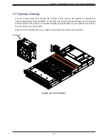
Page 63: ...s controlled by system temperature using the BMC If a fan fails the remaining fans will ramp up to full speed and the system will continue to operate Replace any failed fan at your earliest convenience with the same type and model Make sure the chassis top cover makes a good seal for proper air circulation Figure 3 8 Fan Positions Release Tab ...

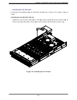
Page 64: ...ds Air shrouds concentrate airflow to maximize fan efficiency They do not require screws to install Installing the Standard Air Shroud Position the air shroud as illustrated in the figure below sliding the front over the edge of the fan tray Align the holes in the edge of the shrouds with the hold in the fan tray ...

Page 65: ...n LED displays the status Solid Green When illuminated indicates that the power supply is on Blinking Green When blinking indicates that the power supply is plugged in and turned off by the system Blinking Amber When blinking indicates that the power supply has a warning condition and continues to operate Solid Amber When illuminated indicates that the power supply is plugged in and is in an abnor...

Page 66: ...66 Chapter 3 Maintenance and Component Installation Figure 3 10 Replacing the Power Supply Release Tab 3 PWS1 PWS2 ...

Page 67: ...on 3 1 and remove the cover 2 Unscrew and remove the chassis slot cover 3 Insert the expansion card into a slot on the motherboard while aligning the expansion card backplate with the open slot in the rear of the chassis Secure with a screw 4 Replace the cover and power 1 2 2 3 Expansion Card Chassis Slots Item Description 1 AIOM PCIe 4 0 x16 CPU1 2 SLOT2 3 PCIe 4 0 x16 CPU2 3 SLOT1 PCIe 4 0 x16 C...

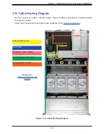
Page 68: ...this section to route or reroute cables Proper routing is important to maintain airflow through the system Cable part numbers and descriptions are available at the Online Cable Matrix Backplane 1 BPN SAS3 846EL1 N4 Manual Default SATA Cable Backplane Power Cable Front Panel Control Cable SAS Cable Optional NVMe Cable ...

Page 69: ... 4 6 Rear I O Ports Description Description 1 COM Port 1 4 USB0 3 0 2 VGA Port 5 USB1 3 0 3 Dedicated BMC LAN Port 6 UID Switch BMC Reset VGA Connections There is one VGA connection in your system The rear VGA port VGA is located on the rear I O panel of the motherboard The VGA connection provides analog interface support between the computer and the video displays Refer to the layout below for th...

Page 70: ... USB1 located on the rear I O panel of the motherboard One internal USB 3 0 vertical Type A connector is located at USB2 These USB ports and connector can be used for USB support via USB cables not included Rear I O Panel USB 3 0 Ports USB0 USB1 Pin Definitions Pin Definition Pin Definition 1 VBUS1 10 VBUS2 2 USB2_N_1 11 USB2_N_2 3 USB2_P_1 12 USB2_P_2 4 GND 13 GND 5 USB3_RN_1 14 USB3_RN_2 6 USB3_...

Page 71: ...elow Also refer to the BMC User s Guide posted on our website at http www supermicro com for more information on BMC UID BMC Reset Switch JUIDB1 Features Settings When Used as a UID LED Switch When Used as a BMC Reset Switch Work w Rear UID LED UID_LED1 Front UID LED JF1 Pins 7 8 Work with BMC Heartbeat LED LEDM1 Rear UID LED UID_LED1 Blue Unit identified BMC Heartbeat LED LEDM1 Blinking Green BMC...

Page 72: ...te power supply to the motherboard be sure to connect the 24 pin ATX PWR and 8 pin PWR connectors to the power distribution board PDB Failure to do so may void the manufacturer warranty on your PDB and motherboard ATX Power 24 pin Connector Pin Definitions Pin Definition Pin Definition 13 3 3V 1 3 3V 14 NC 2 3 3V 15 Ground 3 Ground 16 PS_ON 4 5V 17 Ground 5 Ground 18 Ground 6 5V 19 Ground 7 Ground...

Page 73: ... Pin Definition 1 5V 2 No Connection 3 No Connection 4 Speaker Speaker Header A speaker header located at JD1 can be used in conjunction with an external speaker optional Use an appropriate cable to connect this header to an external speaker or buzzer for support of BIOS beep codes and system alarms Refer to the table below for pin definitions S SGPIO Header The S SGPIO Serial General Purpose Inpu...

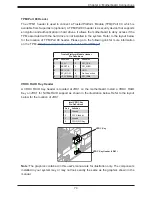
Page 74: ...s not installed in the system Refer to the layout below for the location of TPM Port 80 header Please go to the following link for more information on the TPM http www supermicro com manuals other TPM pdf VROC RAID Key Header A VROC RAID Key header is located at JRK1 on the motherboard Install a VROC RAID Key on JRK1 for NVMe RAID support as shown in the illustration below Refer to the layout belo...

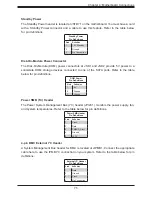
Page 75: ... SATA ports Refer to the table below for pin definitions DOM Power Pin Definitions Pin Definition 1 5V 2 Ground 3 Ground Power SMB I2 C Header The Power System Management Bus I2 C header JPI2C1 monitors the power supply fan and system temperatures Refer to the table below for pin definitions Power SMB Header Pin Definitions Pin Definition 1 Clock 2 Data 3 PMBUS_Alert 4 Ground 5 3 3V 4 pin BMC Exte...

Page 76: ...s hot plug support via a dedicated SMBus interface This feature is only available for a Supermicro complete system with an SMCI proprietary NVMe add on card and a proper cable installed Refer to the table below for pin definitions NVMe SMBus Header Pin Definitions Pin Definition 1 Data 2 Ground 3 Clock 4 3 3V SlimSAS NVMe Connectors Four SlimSAS NVMe connectors P1_NVME0 P1_NVME3 provide eight NVMe...

Page 77: ...ctors are designed specifically for use with Supermicro chassis Refer to the table below for pin definitions of JFP1 Regarding the pin functions refer to Section 2 6 JFP1 and JF1 have the same pin functions although the pin numbers might differ Front Control Panel Header for FFC FPC Cable Pin Definitions Pin Definition 20 Ground 19 Power Fail 18 5V 17 5V 16 5V 15 3 3 Pull Up 14 Ground 13 FP Sensor...

Page 78: ...e designed specifically for use with Supermicro chassis Refer to the figure below for the descriptions of the front control panel buttons and LED indicators Power Button Blue LED_Cathode_UID NIC1 Activity LED Reset Button HDD LED FP PWR LED ID_UID 3 3V Stby Ground 19 Ground 20 1 2 Ground Power Fail for LED6 NIC2 Link LED NMI 3 3V Red OH Fan Fail PWR Fail for LED5 Blue UID LED 3 3V JF1 Red Blue NIC...
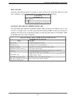
Page 79: ...icators Event Power LED1 HDD LED2 LAN LED3 4 UID LED5 Information LED5 Power Fail LED6 Power On Solid On HDD Activity Blinking NIC Activity Blinking Overheat Solid On Fan Fail Blinking at 1Hz Power Fail Blinking at 1 4Hz Solid On Local UID On Solid On Remote UID On Blinking 1Hz Checking BMC BIOS Blinking at 4HZ Recovering Updating BMC Blinking at 4HZ BMC 2 Blinks at 4Hz 1 Pause at 2Hz on on off of...

Page 80: ...fer to the tables below for more information Reset Button The Reset Button connection is located on pins 3 and 4 of JF1 Momentarily contacting both pins will reset the system Refer to the table below for pin definitions Power Button Pin Definitions Pin 1 Pin 2 of JF1 Status Event Green solid on System power on BMC BIOS blinking green at 4Hz BMC BIOS checking BIOS blinking green at 4Hz BIOS recover...

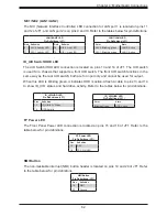
Page 81: ...king red 10Hz FP red LED CPLD recovery mode error s Solid blue Local UID is activated Use this function to locate a unit in a rack mount environment that might be in need of service Blinking blue 1Hz Remote UID is on Use this function to identify a unit from a remote location that might be in need of service BIOS BMC blinking blue 10Hz BIOS BMC recovery and or update in progress Red Info LED blink...

Page 82: ...tput When this LED is blinking green it indicates HDD is active Attach a cable to pins 13 and 14 to show ID_UID status and hard drive activity Refer to the tables below for pin definitions ID_UID HDD LED Pin Definitions JF1 Pins Definition 13 ID_UID 3 3V Stdby 14 HDD Activity ID_UID HDD LED Pin Definitions JF1 Color State Blinking Green HDD Active LAN1 LAN2 LED Pin Definitions JF1 Color State NIC ...

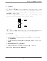
Page 83: ... pin or has been completely removed Connector Pins Jumper Setting 3 2 1 3 2 1 CMOS Clear JBT1 is used to clear CMOS which will also clear any passwords Instead of pins this jumper consists of contact pads to prevent accidentally clearing the contents of CMOS To Clear CMOS 1 First power down the system and unplug the power cord s 2 Remove the cover of the chassis to access the motherboard and remov...

Page 84: ...tem Reset Jumper Settings Jumper Setting Definition Pins 1 2 UID Enabled Pins 2 3 System Reset Default Watchdog Watchdog JWD1 is a system monitor that can reboot the system when a software application hangs Close pins 1 2 to reset the system if an application hangs Close pins 2 3 to generate a non maskable interrupt NMI signal for the application that hangs Refer to the table below for jumper sett...

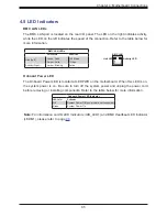
Page 85: ...linking Active BMC LAN Activity LED Link LED LAN 1 LAN 2 IPMI LAN X8ST3 F Onboard Power LED The Onboard Power LED is located at LEDPWR on the motherboard When this LED is on the system power is on Be sure to turn off the system power and unplug the power cord before removing or installing components Refer to the table below for more information Onboard Power LED Indicator LED Color Definition Off ...

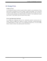
Page 86: ...Ie 4 0 x4 M 2 NVMe SSDs or SATA 3 0 SSDs in the 2280 and 22110 form factors 4 6 Storage Ports S SATA 3 0 Ports The X12DSC A6 has four S SATA 3 0 ports S SATA0 S SATA3 on the motherboard These SATA ports are supported by the C621A chipset S SATA0 and S SATA1 can be used with Supermicro SuperDOMs which are orange SATA DOM connectors with power pins built in and do not require external power cables S...

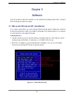
Page 87: ...lling the Windows OS and the RAID driver Refer to the RAID Configuration User Guides posted on our website at www supermicro com support manuals Installing the OS 1 Create a method to access the MS Windows installation ISO file That might be a DVD perhaps using a USB flash or media drive or the BMC KVM console 2 Boot from a bootable device with Windows OS installation You can see a bootable device...

Page 88: ...river browse the USB flash drive for the proper driver files For RAID choose the SATA sSATA RAID driver indicated then choose the storage drive on which you want to install it For non RAID choose the SATA sSATA AHCI driver indicated then choose the storage drive on which you want to install it 4 Once all devices are specified continue with the installation 5 After the Windows OS installation has c...

Page 89: ...ed Another option is to go to the Supermicro website at www supermicro com Products Find the product page for your motherboard and Download the Latest Drivers and Utilities Insert the flash drive or disk and the screenshot shown below should appear Figure 5 3 Driver and Tool Installation Screen Note Click the icons showing a hand writing on paper to view the readme files for each item Click the co...

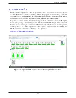
Page 90: ...e Network Management Protocol SNMP SuperDoctor 5 comes in local and remote management versions and can be used with Nagios to maximize your system monitoring needs With SuperDoctor 5 Management Server SSM Server you can remotely control power on off and reset chassis intrusion for multiple systems with SuperDoctor 5 or BMC SuperDoctor 5 Management Server monitors HTTP FTP and SMTP services to opti...

Page 91: ... related to BMC For general documentation and information on BMC visit our website at www supermicro com en solutions management software bmc resources BMC ADMIN User Password For security each system is assigned a unique default BMC password for the ADMIN user This can be found on a sticker on the chassis and a sticker on the motherboard The sticker also displays the BMC MAC address Figure 5 5 BM...

Page 92: ...ge Control Card and Cable s TPM security module Intel VROC RAID Key 6 1 Additional Storage Drives The system supports 24 hot swap 3 5 SATA3 SAS3 drives accessible from the chassis front 6 2 Storage Control Card and Cable s Supermicro offers storage controller cards for various data protection and drive RAID levels Please refer to the product page for the latest cards and add on options ...

Page 93: ...ed to connect a Trusted Platform Module TPM A TPM is a security device that supports encryption and authentication in hard drives It enables the motherboard to deny access if the TPM associated with the hard drive is not installed in the system Details and installation procedures are at http www supermicro com manuals other TPM pdf AOM TPM 9670V AOM TPM 9671V ...

Page 94: ... Storage Technology enterprise Intel RSTe Driver for Linux Windows https downloadcenter intel com download 28108 Intel Virtual RAID on CPU Intel VROC and Intel Rapid Storage Technology enterprise Intel RSTe Driver for Windows To enable Intel VROC a hardware key must be inserted on the motherboard and the ap propriate processor s Virtual Management Devices must be enabled in the BIOS setup It is po...

Page 95: ...The key options are Intel VROC Keys VROC Package Description Part Number Intel MM Number Standard RAID 0 1 10 Supports 3rd party SSDs AOC VROCSTNMOD 951605 Premium RAID 0 1 5 10 Supports 3rd party SSDs AOC VROCPREMOD 951606 Intel SSD only RAID 0 1 5 10 Supports Intel SSDs only AOC VROCINTMOD 956822 Additional Information Additional information is available on the product page for the Supermicro ad...

Page 96: ...ns 2 Switch to Advanced Chipset Configuration North Bridge IIO Configuration Intel VMD Technology Figure 6 2 BIOS Selecting VMD Mode You can select a mode The default is Auto The VMD switch enables VMD mode for all NVMe ports despite the presence of the VROC key The Manual switch allows the user to choose devices on which to enable VMD The onboard M 2 NVMe from PCH is located in the CPU1 section T...

Page 97: ...Optional Components Figure 6 3 BIOS Manual Mode Example your server may look different 3 Select the desired PStack to Enable or Disable the corresponding Intel VMD controller Figure 6 4 BIOS Enabling VMD for Pstack0 ...

Page 98: ... Capability can also be Enabled or Disabled Figure 6 5 BIOS Enabling VMD Functionality per Slot 5 Repeat steps 3 and 4 for each PStack on each CPU to be enabled or disabled In this example we enabled CPU1 Slot1 Figure 6 11 and CPU2 Slot5 Figure 6 12 four U 2 form factor SSDs as well as CPU1 M 2 C 1 and CPU1 M2 C 2 two M 2 form factor SSDs Figure 6 6 BIOS Enabling CPU1 Example ...

Page 99: ... without first deleting the associated existing RAID volume can lead to unexpected behavior This action is strongly not recommended Note The effects of physically changing or swapping a CPU on the VMD controller enablement has not yet been thoroughly tested or documented 7 Switch to Advanced Intel R Virtual RAID on CPU All Intel VMD Controllers Create RAID Volume 8 Set Name 9 Set RAID Level ...

Page 100: ...24 disks RAID1 Select only two disks RAID5 Select at least three 3 24 disks RAID10 Select only four disks 12 Select Strip Size Default 64KB 13 Select Create Volume 14 If another RAID is needed start again at step 9 15 Press F4 to save and reboot Figure 6 8 Created Volume without enabling RAID spanned over VMD controller Figure 6 9 Created Volume with enabling RAID spanned over VMD controller ...

Page 101: ...e device Hot plug Physically install the device ESXi will automatically discover NVMe SSDs but a manual scan may be required in some cases Related Information Links 1 https kb vmware com s article 2151404 2 https docs vmware com en VMware vSphere 6 5 com vmware vsphere storage doc GUID 1B56EF97 F60E 4F21 82A7 8F2A7294604D html 3 https docs vmware com en VMware vSphere 6 5 com vmware vsphere storag...

Page 102: ... other service extensions Direct Links for the SSG 620P E1CR24 H L System Web SSG 620P E1CR24H and SSG 620P E1CR24L specifications page X12DSC A6 motherboard page for links to the Quick Reference Guide User Manual validated storage drives etc BPN SAS3 846EL1 N4 Backplane Manual Direct Links for General Support and Information Frequently Asked Questions Add on card descriptions TPM User Guide Gener...

Page 103: ...to BMC For general documentation and information on BMC please visit our website at https www supermicro com en solutions management software bmc resources Figure 7 2 BMC Sample For validated memory use our Product Resources page Product Matrices page for links to tables summarizing specs for systems motherboards power supplies riser cards add on cards etc Security Center for recent security notic...

Page 104: ...ke sure AC power is being supplied to the power supply Check that the power cord is plugged into a power outlet that supply 100 127Vac 50 60Hz 12 15A and 200 240vac 50 60Hz 7 8 5A Turn the power switch on and off to test the system PWRLED BMC CODE BIOS LICENSE BAR CODE DESIGNED IN USA X12DSC A6 REV 1 00 1 CPU1 CPU2 P1 DIMMB1 P1 DIMMA1 P1 DIMMD1 P1 DIMMC1 P1 DIMMG1 P1 DIMMH1 P1 DIMME1 P1 DIMMF1 P2 ...

Page 105: ...erboard If there are error beeps clear the CMOS settings by unplugging the power cord and contacting both pads on the CMOS clear jumper JBT1 Refer to Clear CMOS in Chapter 2 2 Remove all components from the motherboard especially the DIMM modules Make sure that system power is on and that memory error beeps are activated 3 Turn on the system with only one DIMM module installed If the system boots ...

Page 106: ... sure that all hard disk drives HDDs work properly Replace the bad HDDs with good ones 4 System cooling Check the system cooling to make sure that all heatsink fans and CPU system fans etc work properly Check the hardware monitoring settings in the BMC to make sure that the CPU and system temperatures are within the normal range Also check the front panel Overheat LED and make sure that it is not ...

Page 107: ...on to make sure that it works properly Replace a bad component with a good one 5 Check and change one component at a time instead of changing several items at the same time This will help isolate and identify the problem 6 To find out if a component is good swap this component with a new one to see if the system will work properly If so then the old component is bad You can also install the compon...

Page 108: ...nt to provide information to support staff You can download a crash dump of status information using BMC Check the BMC Error Log 1 Access the BMC web interface 2 Click the Server Health tab then Event Log to verify an IERR error Figure 7 3 BMC Event Log In the event of an IERR the BMC executes a crash dump You must download the crash dump and save it ...

Page 109: ...he system Notes Clearing CMOS will also clear all passwords Do not use the PW_ON connector to clear CMOS JBT1 contact pads 7 6 BMC Reset The BMC can be reset using the UID button Reset Press and hold the button After six seconds the LED blinks at 2Hz The BMC resets and the reset duration is 250 ms Then the BMC starts to boot Restore factory default configuration Hold the button for twelve seconds ...

Page 110: ... you still cannot resolve the problem include the following information when contacting us for technical support System motherboard and chassis model numbers and PCB revision number BIOS release date version this can be seen on the initial display when your system first boots up System configuration An example of a Technical Support form is posted on our website Distributors For immediate assistan...

Page 111: ...ailure due to the alteration misuse abuse or improper maintenance of products During the warranty period contact your distributor first for any product problems Vendor Support Filing System For issues related to Intel use the Intel IPS filing system https www intel com content www us en design support ips training welcome html For issues related to Red Hat Enterprise Linux since it is a subscripti...

Page 112: ...com Europe Address Super Micro Computer B V Het Sterrenbeeld 28 5215 ML s Hertogenbosch The Netherlands Tel 31 0 73 6400390 Fax 31 0 73 6416525 Email sales supermicro nl General Information support supermicro nl Technical Support rma supermicro nl Customer Support Website www supermicro nl Asia Pacific Address Super Micro Computer Inc 3F No 150 Jian 1st Rd Zhonghe Dist New Taipei City 235 Taiwan R...

Page 113: ... in the Supermicro chassis T h e s e w a r n i n g s m a y a l s o b e f o u n d o n o u r w e b s i t e a t http www supermicro com about policies safety_information cfm Warning Definition 警告の定義 この警告サインは危険を意味します 人身事故につながる可能性がありますので いずれの機器でも動作させる前に 電気回路に含まれる危険性に注意して 標準的な事故防止策に精通して下さい 此警告符号代表危险 您正处于可能受到严重伤害的工作环境中 在您使用设备开始工作之前 必须充分意识到触电 的危险 并熟练掌握防止事故发生的标准工作程序 请根据每项警告结尾的声明号码找到此设 备的安全性警告说明的翻译文本 此警告符號代...

Page 114: ...l número que le ayudará a encontrar el texto traducido en el apartado de traducciones que acompaña a este dispositivo GUARDE ESTAS INSTRUCCIONES IMPORTANTES INFORMATIONS DE SÉCURITÉ Ce symbole d avertissement indique un danger Vous vous trouvez dans une situation pouvant entraîner des blessures ou des dommages corporels Avant de travailler sur un équipement soyez conscient des dangers liés aux cir...

Page 115: ... risico s en dient u op de hoogte te zijn van de standaard procedures om ongelukken te voorkomen Gebruik de nummers aan het eind van elke waarschuwing om deze te herleiden naar de desbetreffende locatie BEWAAR DEZE INSTRUCTIES Installation Instructions Warning Read the installation instructions before connecting the system to the power source 設置手順書 システムを電源に接続する前に 設置手順書をお読み下さい 警告 将此系统连接电源前 请先阅读安装说明...

Page 116: ...내를 읽어주십시오 Waarschuwing Raadpleeg de installatie instructies voordat u het systeem op de voedingsbron aansluit サーキッ ト ブレーカー この製品は 短絡 過電流 保護装置がある建物での設置を前提としています 保護装置の定格が250 V 20 Aを超えないこ とを確認下さい 警告 此产品的短路 过载电流 保护由建筑物的供电系统提供 确保短路保护设备的额定电流不大于 250V 20A 警告 此產品的短路 過載電流 保護由建築物的供電系統提供 確保短路保護設備的額定電流不大於 250V 20A Warning This product relies on the building s installation for short circuit overcurrent protectio...

Page 117: ...ension ce produit dépend de l installation électrique du local Vérifiez que le courant nominal du dispositif de protection n est pas supérieur à 250 V 20 A 경고 이 제품은 전원의 단락 과전류 방지에 대해서 전적으로 건물의 관련 설비에 의존합니다 보호장치의 정격이 반드시 250V 볼트 20A 암페어 를 초과하지 않도록 해야 합니다 Waarschuwing Dit product is afhankelijk van de kortsluitbeveiliging overspanning van uw electrische installatie Controleer of het beveiligde apara...

Page 118: ...r zu entfernen Advertencia El sistema debe ser disconnected de todas las fuentes de energía y del cable eléctrico quitado de los módulos de fuente de alimentación antes de tener acceso el interior del chasis para instalar o para quitar componentes de sistema Attention Le système doit être débranché de toutes les sources de puissance ainsi que de son cordon d alimentation secteur avant d accéder à ...

Page 119: ...an systeem onderdelen dient u alle spanningsbronnen en alle stroomkabels aangesloten op de voeding en van de behuizing te verwijderen امداد وحدة من انكهرباء سهك انت ز وإ انطاقت مصادر جميع من اننظاو فصم يجب قبم انطاقت الجهاز مكىناث انت ز إ أو نتثبيج نههيكم انداخهيت امنناطق إىن انىصىل חשמלי ניתוק מפני אזהרה אזהרה מהספק החשמלי כבל את להסיר ויש החשמל מקורות מכל המערכת את לנתק יש רכיבים הסרת או התקנת ל...

Page 120: ...stattet werden Advertencia Solamente el personal calificado debe instalar reemplazar o utilizar este equipo Attention Il est vivement recommandé de confier l installation le remplacement et la maintenance de ces équipements à des personnels qualifiés et expérimentés 경고 훈련을 받고 공인된 기술자만이 이 장비의 설치 교체 또는 서비스를 수행할 수 있습니다 Waarschuwing Deze apparatuur mag alleen worden geïnstalleerd vervangen of hersteld...

Page 121: ...eguridad Attention Cet appareil doit être installée dans des zones d accès réservés L accès à une zone d accès réservé n est possible qu en utilisant un outil spécial un mécanisme de verrouillage et une clé ou tout autre moyen de sécurité アクセス制限区域 このユニッ トは アクセス制限区域に設置されるこ とを想定しています アクセス制限区域は 特別なツール 鍵と錠前 その他のセキュリティの手段を用いてのみ出入り が可能です Restricted Area 警告 此部件应安装在限制进出的场所 限制进出的场所指只能通过使用特殊工具 锁和钥匙或其它 安全手段进...

Page 122: ...下さい 使用済電池は製造元の指示に従って処分して下さ い 警告 电池更换不当会有爆炸危险 请只使用同类电池或制造商推荐的功能相当的电池更换原有电 池 请按制造商的说明处理废旧电池 警告 電池更換不當會有爆炸危險 請使用製造商建議之相同或功能相當的電池更換原有電池 請按 照製造商的說明指示處理廢棄舊電池 Warning There is the danger of explosion if the battery is replaced incorrectly Replace the battery only with the same or equivalent type recommended by the manufacturer Dispose of used batteries according to the manufacturer s instructions מוגבלת ...

Page 123: ...n Batterie besteht Explosionsgefahr Ersetzen Sie die Batterie nur durch den gleichen oder vom Hersteller empfohlenen Batterietyp Entsorgen Sie die benutzten Batterien nach den Anweisungen des Herstellers Attention Danger d explosion si la pile n est pas remplacée correctement Ne la remplacer que par une pile de type semblable ou équivalent recommandée par le fabricant Jeter les piles usagées confo...

Page 124: ...arnung Dieses Gerät kann mehr als eine Stromzufuhr haben Um sicherzustellen dass der Einheit kein trom zugeführt wird müssen alle Verbindungen entfernt werden Advertencia Puede que esta unidad tenga más de una conexión para fuentes de alimentación Para cortar por completo el suministro de energía deben desconectarse todas las conexiones Attention Cette unité peut avoir plus d une connexion d alime...

Page 125: ... Use caution when servicing 경고 이 장치에는 한 개 이상의 전원 공급 단자가 연결되어 있을 수 있습니다 이 장치에 전원을 차단하기 위해서는 모든 연결 단자를 제거해야만 합니다 Waarschuwing Deze eenheid kan meer dan één stroomtoevoeraansluiting bevatten Alle aansluitingen dienen verwijderd te worden om het apparaat stroomloos te maken אחד מספק יותר קיים אם אזהרה לרוקן מנת על החיבורים כל את להסיר יש ספק של אחד מחיבור יותר יש ליחדה היחידה את الطاقة امداد بوحدات ات...

Page 126: ... קיימת העבודה اللىحة عىل املىجىدة أوالطاقة الكهزبايئ التيار مه خطز هناك الجهاس هذا خدمة عند ا ر حذ كه يعمل النظام يكىن عندما Warnung Wenn das System in Betrieb ist treten auf der Rückwandplatine gefährliche Spannungen oder Energien auf Vorsicht bei der Wartung Advertencia Cuando el sistema está en funcionamiento el voltaje del plano trasero es peligroso Tenga cuidado cuando lo revise Attention Lor...

Page 127: ...ئية املعدات تركيب بالكهرباء Comply with Local and National Electrical Codes 地方および国の電気規格に準拠 機器の取り付けはその地方および国の電気規格に準拠する必要があります Warnung Die Installation der Geräte muss den Sicherheitsstandards entsprechen Advertencia La instalacion del equipo debe cumplir con las normas de electricidad locales y nacionales Attention L équipement doit être installé conformément aux normes électriques nationales et lo...

Page 128: ... de este producto debe seguir todas las leyes y reglamentos nacionales Attention La mise au rebut ou le recyclage de ce produit sont généralement soumis à des lois et ou directives de respect de l environnement Renseignez vous auprès de l organisme compétent Waarschuwing De uiteindelijke verwijdering van dit product dient te geschieden in overeenstemming met alle nationale wetten en reglementen 경고...

Page 129: ...s Se tenir a l ecart des lames du ventilateur Il est possible que les ventilateurs soient toujours en rotation lorsque vous retirerez le bloc ventilateur du châssis Prenez garde à ce que doigts tournevis et autres objets soient éloignés du logement du bloc ventilateur Hot Swap Fan Warning Warning Hazardous moving parts Keep away from moving fan blades The fans might still be turning when you remov...

Page 130: ...움직이는 위험한 부품 회전하는 송풍 날개에 접근하지 마세요 섀시로부터 팬 조립품을 제거할 때 팬은 여전히 회전하고 있을 수 있습니다 팬 조림품 외관의 열려있는 부분들로부터 손가락 및 스크류드라이버 다른 물체들이 가까이 하지 않도록 배치해 주십시오 Waarschuwing Gevaarlijk bewegende onderdelen Houd voldoende afstand tot de bewegende ventilatorbladen Het is mogelijk dat de ventilator nog draait tijdens het verwijderen van het ventilatorsamenstel uit het chassis Houd uw vingers schroevendraaiers en eventuele ...

Page 131: ...funktionen oder Feuer verursachen Die Richtlinien untersagen das Nutzen von UL oder CAS zertifizierten Kabeln mit UL CSA gekennzeichnet an Geräten oder Produkten die nicht mit Supermicro gekennzeichnet sind Advertencia Cuando instale el producto utilice la conexión provista o designada o procure cables Cables de alimentación y adaptadores de CA que cumplan con los códigos locales y los requisitos ...

Page 132: ...eerde Kabels met UL CSA in de code voor elke andere toepassing dan de door Supermicro hiervoor beoogde Producten םילבכ םיילמשח ימאתמו AC הרהזא רשאכ םיניקתמ תא רצומה שי שמתשהל םילבכב םיקפס םימאתמו AC רשא ושכרנ וא ומאתוה ךרוצל הנקתהה רשאו ומאתוה תושירדל תוחיטבה תוימוקמה ללוכ הדימ הנוכנ לש לבכה עקתהו שומיש לכב לבכ וא םאתמ גוסמ רחא לולע םורגל הלקתל וא רצק ילמשח םאתהב יקוחל שומישה ירישכמב למשחה יקוחו ת...

Page 133: ...s disk on module ports PCI Expansion Slots Three PCIe 4 0 x16 low profile One PCIe 4 0 x16 AIOM see Section 3 9 for details Input Output LAN Two RJ45 10G BASE T one RJ45 dedicated BMC LAN port USB Four USB 3 0 ports Rear One VGA port Rear One COM port Rear Motherboard X12DSC A6 12 L x 13 W 305mm x 330mm Chassis CSE 826S2TS R1K62P1 4U WxHxD 17 2 x 7 x 26 5 in 437 x 178 x 673 mm System Cooling Five ...

Page 134: ... 3 BS EN 61000 4 2 BS EN 61000 4 3 BS EN 61000 4 4 BS EN 61000 4 5 BS EN 61000 4 6 BS EN 61000 4 8 BS EN 61000 4 11 Product Safety 2014 35 EU LVD Directive UL CSA 62368 1 USA and Canada Electrical Equipment Safety Regulations 2016 IEC BS EN 62368 1 Environment 2011 65 EU RoHS Directive EC 1907 2006 REACH 2012 19 EU WEEE Directive Warning This product can expose you to chemicals including lead know...

Reviews: