background image

2-5

Chapter 2: Blade System

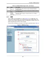
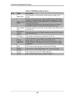
After gaining access to the GbE switch(es), you can use the reset button to reset their 
configurations to the default settings. The reset button will reset all GbE switch 
configurations, including IP address and so on.

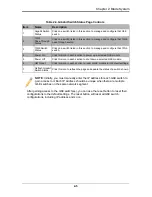
Table 2-3. Gibabit Switch Status Page Controls 

Item

Name

Description

1

Gigabit Switch 
Status

Click on a switch listed in this section to manage and configure that GbE 
switch.

2

10Gb 
Pass-Through 
Status

Click on a switch listed in this section to manage and configure that 10Gb 
pass-through switch.

3

10Gb Switch 
Status

Click on a switch listed in this section to manage and configure that 10Gb 
switch.

4

Power On

Click this icon in each section to power up a selected GbE module.

5

Power Off

Click this icon in each section to shut down a selected GbE module.

6

HW Reset

Click this icon in each section to reset a GbE module to its default settings.

7

Refresh Gigabit 
Switch Status

Click this icon to refresh the page and update the status of a switch shown.

NOTE: 

Initially, you must manually enter the IP address for each GbE switch to 

gain access to it. Each IP address should be unique when there are multiple 
GbE switches on the same network segment.

Summary of Contents for Web-based Management Utility

Page 1: ...Web based Management Utility For the SuperBlade System User s Manual Revison 1 0b ...

Page 2: ...utes Super Micro s total liability for all claims will not exceed the price paid for the hardware product FCC Statement This equipment has been tested and found to comply with the limits for a Class A digital device pursuant to Part 15 of the FCC Rules These limits are designed to provide reasonable protection against harmful interference when the equipment is operated in a commercial environment ...

Page 3: ...3 Virtual Media This chapter covers the menu options and controls for the Virtual Media menu Chapter 4 System Health This chapter covers the menu options and controls for the System Health menu Chapter 5 User Management This chapter covers the menu options and controls for the User Management menu Chapter 6 KVM Settings This chapter covers the menu options and controls for the KVM Settings menu Ch...

Page 4: ...ddress Super Micro Computer B V Het Sterrenbeeld 28 5215 ML s Hertogenbosch The Netherlands Tel 31 0 73 6400390 Fax 31 0 73 6416525 Email sales supermicro nl General Information support supermicro nl Technical Support rma supermicro nl Customer Support Asia Pacific Address Super Micro Computer Inc 4F No 232 1 Liancheng Rd Chung Ho 235 Taipei County Taiwan R O C Tel 886 2 8226 3990 Fax 886 2 8226 3...

Page 5: ...iniBand Switch 2 6 2 5 CMM 2 7 Chapter 3 Virtual Media 3 1 3 1 Floppy Disk 3 2 3 2 CD ROM 3 3 3 3 Drive Redirection 3 4 3 4 Options 3 5 Chapter 4 System Health 4 1 4 1 System Event Log 4 1 4 2 Alert Settings 4 2 IPMI Filter Edit 4 3 IPMI Policy List Edit 4 3 IPMI LAN Destination Edit 4 4 Chapter 5 User Management 5 1 5 1 Change Password 5 1 5 2 Users Groups 5 2 5 3 Permissions 5 4 Chapter 6 KVM Se...

Page 6: ...on 8 1 8 2 Event Log 8 2 8 3 Update Firmware 8 3 8 4 Unit Reset 8 4 Chapter 9 Remote Console 9 1 9 1 Remote Console Interface Page 9 2 9 2 Drive Redirection Page 9 3 9 3 Remote Console Options 9 4 Monitor Only 9 4 Exclusive Access 9 4 Readability Filter 9 4 Scaling 9 5 Local Cursor 9 5 Chat Window 9 5 Video Settings 9 6 Soft Keyboard 9 6 Local Keyboard 9 7 Hotkeys 9 7 ...

Page 7: ...age 4 4 Figure 5 1 Change Passwords Page 5 1 Figure 5 2 Users and Groups Page 5 2 Figure 5 3 Permissions Page 5 4 Figure 6 1 User Console Page 6 2 Figure 6 2 Keyboard Mouse Page 6 4 Figure 7 1 Network Page 7 2 Figure 7 2 Dynamic DNS Settings Page 7 4 Figure 7 3 Security Page 7 6 Figure 7 4 Device Settings Event Log Page 7 8 Figure 8 1 Device Information Page 8 1 Figure 8 2 Maintenance Event Log Li...

Page 8: ...Web based Management Utility User s Manual viii Notes ...

Page 9: ...ols 3 5 Table 4 1 System Event Log Page Controls 4 1 Table 5 1 Change Password Page Controls 5 1 Table 5 2 Users and Groups Page Controls 5 2 Table 5 3 Permissions Page Controls 5 4 Table 6 1 User Console Page Controls 6 2 Table 6 2 Keyboard Mouse Page Controls 6 4 Table 7 1 Network Page Controls 7 2 Table 7 2 Dynamic DNS Settings Page Controls 7 4 Table 7 3 Security Page Controls 7 6 Table 7 4 De...

Page 10: ...Web based Management Utility User s Manual x Notes ...

Page 11: ... hard drives or ISO images on a shared network drive to a blade server Supported Browsers The following browsers have been tested for use with the Web based Management Utility It is recommended that you use the most current revision of the browser you choose The minimum browser revisions supported by the Web based Management Utility are shown below Internet Explorer 7 Firefox 2 0 0 7 Netscape 9 03...

Page 12: ...ram see Chapter 7 Device Settings on page 7 1 1 2 Home Page Figure 1 1 and Table 1 2 respectively display the WEB BASED MANAGEMENT UTILITY HOME PAGE and its controls Figure 1 1 Home Page Table 1 1 Address Defaults Default Description Default IP Address 192 168 100 100 Default Gateway Address 0 0 0 0 Default Subnet Mask 255 255 255 0 Default username ADMIN Default password ADMIN 1 6 4 3 2 5 ...

Page 13: ...gout Click on this icon to log out See Section 1 3 for details 5 Refresh Click on this icon to refresh the remote console preview page 6 Main Menu Icons Use these icons to initiate the various functions in the Web based Management Utility See Section for details Table 1 3 Main Menu Icons Icon Description Click this icon for remote access and management of individual blade modules See Chapter 2 for...

Page 14: ...Web based Management Utility User s Manual 1 4 Notes ...

Page 15: ...allows you to perform various functions as shown in Figure 2 1 and described in Table 2 1 To perform a function first click the box es next to the blade s you wish to issue a command to and then click the command button below You can also click on any of the individual blades listed for a remote console that brings up a page with details about that particular blade The last column for the Blade St...

Page 16: ...icon to turn on the UID LED of a selected blade module 5 UID Off Click this icon to turn off the UID LED of a selected blade module 6 KVM Click on this icon to initiate Remote KVM over IP and remotely operate a selected blade module 7 Graceful Shutdown Click to send a selected blade module into an S5 sleep state 8 CPU Pwr Usage Click this icon if you want to set a selected blade unit s CPU power u...

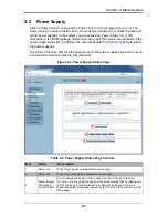
Page 17: ...a function first click the box es next to the power supplies you wish to issue a command to and then click the command icon Figure 2 2 Power Supply Status Page Table 2 2 Power Supply Status Page Controls Item Name Description 1 Power On Click this to power up a selected power supply 2 Power Off Click this to shut down a selected power supply 3 Power Supply Fan Speed Control Option If you change th...

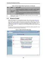
Page 18: ...t to the GbE module s you wish to issue a command to and then click the command icon Figure 2 3 Ethernet Switch Status Page 4 Power Supply Fan Speed Control Set to minimum speed by clicking the icon numbered 1 and to maximum speed by clicking the icon numbered 4 The icons numbered 2 and 3 are for incremental increases between the minimum and maximum settings After changing the fan speed you should...

Page 19: ... and configure that 10Gb pass through switch 3 10Gb Switch Status Click on a switch listed in this section to manage and configure that 10Gb switch 4 Power On Click this icon in each section to power up a selected GbE module 5 Power Off Click this icon in each section to shut down a selected GbE module 6 HW Reset Click this icon in each section to reset a GbE module to its default settings 7 Refre...

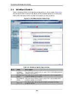
Page 20: ...finiBand Switch Page Controls Item Name Description 1 InfiniBand Switch Status Use this section to select power on power off or reset InfiniBand switches installed in your system 2 IP QDR Switch Status Use this section to select power on power off or reset Infiniband QDR switches installed in your system 3 IP FDR Switch Status Use this section to select power on power off or reset InfiniBand FDR s...

Page 21: ...ere are three commands you may give on this page as described below in Table 2 5 Figure 2 5 CMM Status Page 5 Power Off For each section click on this icon to power off selected InfiniBand switches remotely 6 Reset For each section click on this icon to reset selected InfiniBand switches to their default settings 7 Refresh InfiniBand Switch Status Click this to refresh the page and update the stat...

Page 22: ...me values for the SIMCM internal real time clock 4 Synchronize with NTP Server Click this to synchronize the CMM s real time clock with the NTP Network Time Protocol server 5 UTC Offset This pull down menu allows you to offset the UTC Timer 6 Primary Secondary Time Server Enter the IP Address for the primary or secondary NTP server that you want to synchronize with the CMM internal real time clock...

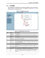
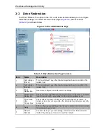
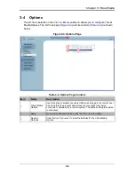
Page 23: ...AL MEDIA menu allows you to configure the various media and drive systems in your SuperBlade system Clicking the VIRTUAL MEDIA icon allows you to access the following pages through its sub menus Floppy Disk CD ROM Drive Redirection Options ...

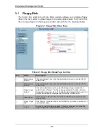
Page 24: ...isplays if any virtual device image has been connected to the remote host 3 Floppy Image Upload This option allows the user to upload the floppy image located in the remote host as floppy The floppy image uploaded should be in binary format with a maximum size of 1 44 MB It will be loaded to the Supermicro SIMCM card and will be emulated to the host as a USB device 4 Virtual Drive Select a drive i...

Page 25: ... decide how to share the CD ROM ISO image file with users in the remote host 4 Virtual Drive Specify the drive that you want to share your data with in the remote host 5 Share Host Key in the IP Address or the name of the system you wish to share data with via Windows Share 6 Share Name Key in the name of the shared folder you wish to share data with in the remote host 7 Path to Image Key in the l...

Page 26: ...connected to the remote host 3 Drive Redirection Use this to configure DRIVE REDIRECTION settings 4 Disable Drive Redirection Check the box to disable Drive Redirection Once this function is disabled local drives will not be accessible for other remote systems users 5 Force Read Only Connections Check this box to allow the data stored in local drives to be read by a remote system but not overwritt...

Page 27: ...ge Controls Item Name Description 1 Virtual Media Options Use this option to disable or enable USB mass storage in the remote host Checking this box prevents data stored in a local drive from being accessed or uploaded by a remote system The default setting is enabled unchecked 2 Apply Once you ve checked the box click the APPLY icon to initiate 3 Reset to Defaults Click this icon if you want to r...

Page 28: ...Web based Management Utility 3 6 Notes ...

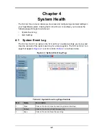
Page 29: ...EVENT LOG option in the SYSTEM HEALTH submenu allows you to view and clear the contents of the system event log for a remote system The SYSTEM EVENT LOG page that appears Figure 4 1 and its controls Table 4 1 are shown below Figure 4 1 System Event Log Page Table 4 1 System Event Log Page Controls Item Name Description 1 Clear Click on this icon to clear the event log delete all entries 2 Refresh ...

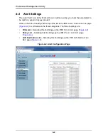
Page 30: ...f the list in the IPMI ALERT CONFIGURATION page Figure 4 2 to sort between the three categories The three headings are Filter List Selecting this link brings up the IPMI FILTER EDIT page Figure 4 3 Policy List Selecting this link brings up the IPMI POLICY LIST EDIT page Figure 4 4 LAN Destination List Selecting this link brings up the IPMI LAN DESTINATION EDIT page Figure 4 5 Figure 4 2 Alert Conf...

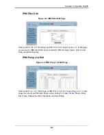
Page 31: ...for Filter Number Status Action Alert Policy and Event Severity IPMI Policy List Edit Clicking the POLICY LIST link brings up IPMI POLICY LIST EDIT page Figure 4 4 In this page you can set an IPMI Alert Policy using controls for Index number Status Policy Set Policy Channel Number Destination and Alert String Figure 4 3 IPMI Filter Edit Page Figure 4 4 IPMI Policy List Edit Page ...

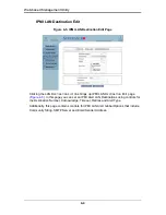
Page 32: ...ge Figure 4 5 In this page you can set an IPMI Alert LAN Destinations using controls for the Destination Number Acknowledge Timeout Retries and Alert Type Additionally this page contains controls for IPMI LAN Alert Global Options that include Community String SMTP Server and Email Sender Address Figure 4 5 IPMI LAN Destination Edit Page ...

Page 33: ...ange Password The CHANGE PASSWORDS page Figure 5 1 is where you can change the password used to access the Web based Management Utility Its controls are shown in Table 5 1 Figure 5 1 Change Passwords Page Table 5 1 Change Password Page Controls Item Name Description 1 New Password Type your new password in the window 2 Confirm New Password Type your new password in this second window to confirm 3 ...

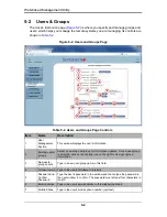
Page 34: ... user group for information updates Once a user group is selected click on the Lookup icon on the right to view user group information 3 New users groups name Type in a new user group name in this field 4 Full user name Type in the user s full name in this field 5 Password and Confirm Password Type the user s password in the window and then retype the password in the next window to confirm The pas...

Page 35: ...on to modify a user s or group information in the User Group Management fields 14 Copy Click on this button to copy a user s or group information in the User Group Management fields Copy User select an existing user from the selection box Enter a new user name in the New User Name window Click the Copy icon and a new user with the name you typed in will be created The properties of the selected us...

Page 36: ...on 1 Show Permissions for User Group Click on the pull down arrow to activate the user group permissions selection menu 2 Update Click this icon to update the permissions information 3 Effective Permissions This field indicates the actual permissions a user or group has 4 User Permissions This field indicates the actual permissions a user has 5 Inherited Group Permission This field indicates the p...

Page 37: ...cellaneous Remote Console Settings This field allows you to specify the following Remote Console Settings Mouse Hotkey This option allows you to use a hot key combination to specify either mouse synchronization mode or the single mouse mode Remote Console Button Keys This field allows you to define button keys for the remote host The button keys allow simulating keystrokes on a remote host or issu...

Page 38: ...he connection line and transmit data accordingly 4 Pre configured This item allows the user to select the data transmission settings from a pre defined options list The pre configured settings will provide the best results because the compression and color depth settings will be adjusted for optimization based on the network speed indicated 5 Network speed Once you ve selected the PRE CONFIGURED o...

Page 39: ... only 9 Start in Exclusive Access Mode Check this box to enable the exclusive access mode immediately upon Remote Console startup which will force all other users connected to the network to close No other users can open the Remote Console until you disable this function or log off 10 Hotkey Enter a hot key combination in the box to specify either mouse synchronization mode or the single mouse mod...

Page 40: ...mit for a key to be pressed by the user 3 Timeout after____msec If the KEY RELEASE TIMEOUT check box has been enabled click on the arrow to select the time out setting in the pull down menu 4 USB Mouse Type For a USB mouse to function properly please select the correct operating system for your system from the pull down menu by clicking on the arrow 5 Mouse Speed Auto Click the check box to allow ...

Page 41: ...he DEVICE SETTINGS menu for configuring network security and log settings for your SuperBlade system Clicking the DEVICE SETTINGS icon allows you to access the following pages through its sub menus Network Dynamic DNS Security Event Log ...

Page 42: ...own and detailed in Table 7 1 Figure 7 1 Network Page Table 7 1 Network Page Controls Item Name Description 1 IP Auto Configuration Click on the pull down menu to select a desired item from the list The options are NONE DHCP and BOOTP 2 Preferred Host Name DHCP only Enter a preferred host name here 3 IP Address Enter the IP address for the remote host here 4 Subnet Mask Enter the subnet mask of th...

Page 43: ...ox to enable SSH access 13 Disable Setup Protocol Check this box to disable the setup protocol function of the SIMBL card 14 LAN Interface Speed Click on the arrow on the right to select a desired LAN interface speed from the pull down menu The options are Auto detect 10 Mbps or 100 Mbps If Auto detect is selected the optimized speed will be set based on the system configurations detected by the O...

Page 44: ...eb site This is the server name where the DDNS Service is registered 3 DNS System If Dynamic DNS is enabled you can select either CUSTOM or DYNAMIC from the pull down menu Select CUSTOM to use your own system as the DNS server Select DYNAMIC to use the pre configured Dynamic DNS as your server 4 Hostname Enter the name you want to use for the remote host server 5 Username Enter the username for th...

Page 45: ...dress for an external system that has been previously entered and saved 10 Apply Click this icon to apply the selections you made 11 Reset to Defaults Click this icon if you want to reset the defaults for the Remote Console button keys Table 7 2 Dynamic DNS Settings Page Controls Item Name Description ...

Page 46: ... the web management utility 2 KVM Encryption This option allows you to configure the encryption of the RFB protocol RFB is used by the remote host to transmit video data displayed in the host monitor to the local administrator machine and to transmit keyboard and mouse data from the local administrator machine back to the remote host If set to OFF no encryption will be used If set to TRY the apple...

Page 47: ...nds to the existing ones 9 Insert Select this option to insert IP Address Mask rules or commands to the existing ones 10 Replace Select this option to replace an old IP Address Mask rule or command with a new one 11 Delete Select this option to delete a part of an existing IP Address Mask rule or command 12 Max Number of Failed Logins Enter the maximum number of failed attempts or failed logins al...

Page 48: ...ble 7 4 Device Settings Event Log Page Controls Item Name Description 1 List Logging Enabled Check this box to activate the event logging list To show the event log list click on EVENT LOG under SYSTEM HEALTH NOTE The maximum number of log list entries is 1 000 events Every entry that exceeds this limit will automatically override the oldest one in the list If the reset button is pressed all loggi...

Page 49: ...il Address Enter the email address that the SMTP event logging data will be sent to 11 Sender Email Address Enter the email address from which the SMTP event logging data is sent 12 SNMP Logging Enabled Check this box to enable SNMP Simple Network Management Protocol logging 13 Destination IP Enter the IP address where the SNMP trap will be sent to 14 Community Enter the name of the community if t...

Page 50: ...Web based Management Utility 7 10 Notes ...

Page 51: ...p the DEVICE INFORMATION page Figure 8 1 which provides system information The controls for this page are detailed in Table 8 1 Figure 8 1 Device Information Page Table 8 1 Device Information Page Controls Item Name Description 1 Device Information This field displays information on the SIMCM card and its firmware 2 View the Data File for Support Click on this link to view the XML file which conta...

Page 52: ...ANCE submenu brings up the MAINTENANCE EVENT LOG LIST page Figure 8 2 This page contains information on events that are recorded by the SIMCM in the order of Date Time Types and Descriptions including the IP address es user s and activities involved Figure 8 2 Maintenance Event Log List Page ...

Page 53: ...age are detailed in Table 8 2 Figure 8 3 Update Firmware Page NOTE This process is not reversible once the firmware is updated so proceed with caution It might take a few minutes to complete this procedure Table 8 2 Update Firmware Page Controls Item Name Description 1 Firmware File Enter the name of the firmware you want to update or click BROWSE to select the file 2 Upload Click on the UPLOAD ic...

Page 54: ...the Keyboard Mouse USB module 2 Reset USB Click the RESET icon to reset the USB module 3 Reset Video Engine Click the RESET icon to reset the Video Engine module 4 Reset Device Click the RESET icon to cold reset the utility s firmware 5 Reset Other Device If your Blade system has a secondary CMM then the Reset Other Device section will be shown As above with the Reset Device icon click this icon t...

Page 55: ...on in the upper left area of the page Blade System Menu Click the BLADE SYSTEM icon on the left of the page then click BLADE in the submenu A page will open with a list of blades The blade units listed are hyperlinks click one of these to open a page giving details on that blade unit In each page you will see a REMOTE CONSOLE PREVIEW pane At the top is a link that reads CLICK TO OPEN Click this li...

Page 56: ...ds to manage the remote server or allow the remote server be controlled and managed by a local user logged in to the remote server see Table 9 1 for a list of controls This function provides a full spectrum of remote console interaction and management Figure 9 1 Remote Console Interface Page Table 9 1 Remote Console Interface Page Item Name Description 1 Drive Page Button Click on this button to o...

Page 57: ...elected 2 Connect ISO Click this button to allow you to redirect an CD DVD ISO image 3 Disconnect Click this button to cancel the connection established between a local drive and a remote server Once you click this button the drive you have selected will not be accessible for remote console interface Local Drive List This pull down menu displays a list of local drives available for remote access S...

Page 58: ...function on or off If MONITOR ONLY is selected the KB MOUSE icon on the lower right corner will be crossed out and the user can only view or monitor remote console activities Also any remote console interaction will no longer be available Exclusive Access With the appropriate permission a user can force other users to quit the remote console and claim the console for their own exclusive use by cli...

Page 59: ...ENT DEFAULT BIG PIXEL and CROSS HAIR The availability of the shapes depends on the Java Virtual Machine used Chat Window This item allows the user to communicate with other users logged in to the same remote host The page below shows a CHAT WINDOW displayed in a scaled down remote console page see Figure 9 4 The window s controls are shown in Table 9 3 Figure 9 4 Chat Window NOTE This item is avai...

Page 60: ...anges Soft Keyboard This item allows the user to use the soft keys that have been pre installed in the Soft Keyboard of the particular language selected Click on SHOW BUTTON to show a soft keyboard which contains pre installed soft keys see Figure 9 6 Click on MAPPING to display a list of major world languages When the language list displays select the language you want to use by clicking on it se...

Page 61: ...nning the remote console host After you have clicked LOCAL KEYBOARD button a language submenu displays When this language list displays select the language you want to use Hotkeys This item allows the user to select a pre defined hot key from a list Once a hot key is selected the command associated with the hot key will be sent to the remote console host for execution After you ve clicked the HOTK...

Page 62: ...Web based Management Utility 9 8 Notes ...
Page 63: ...cted to result in significant injury or loss of life or catastrophic property damage Accordingly Supermicro disclaims any and all liability and should buyer use or sell such products for use in such ultra hazardous applications it does so entirely at its own risk Furthermore buyer agrees to fully indemnify defend and hold Supermicro harmless for and against any and all claims demands actions litig...

Page 64: ...Web based Management Utility User s Manual ...

Reviews: