


5-16
S
UPER
S
ERVER 1027R-73DARF User's Manual
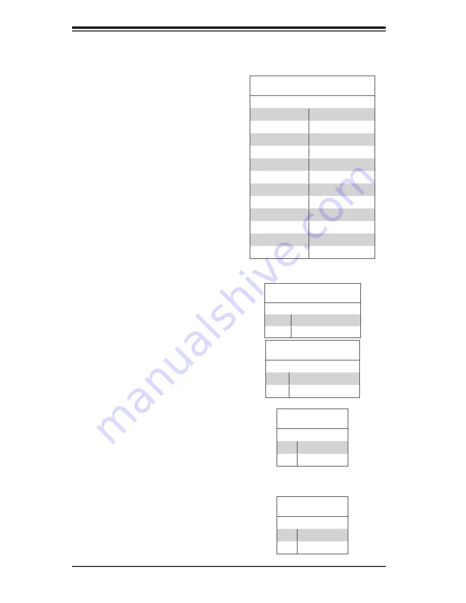
Reset Button
The Reset Button connection is
located on pins 3 and 4 of JF1 and
attaches to the reset switch on the
computer chassis. See p. 5-4 and the
table on the right for pin definitions.
Power Button
The Power On connection is on pins
1 and 2 of JF1. These should be con-
nected to the chassis power button.
See p. 5-4 and the table on the right
for pin definitions.
5-8 Connector Definitions
ATX Power 24-pin Connector
Pin Definitions
Pin# Definition Pin # Definition
13
+3.3V
1
+3.3V
14
-12V
2
+3.3V
15
COM
3
COM
16
PS_ON
4
+5V
17
COM
5
COM
18
COM
6
+5V
19
COM
7
COM
20
Res (NC)
8
PWR_OK
21
+5V
9
5VSB
22
+5V
10
+12V
23
+5V
11
+12V
24
COM
12
+3.3V
Reset Button
Pin Definitions (JF1)
Pin# Definition
3
Reset
4
Ground
Power Button
Pin Definitions (JF1)
Pin# Definition
1
Power Signal
2
Ground
Secondary Power Connector
JPW2 and JPW3 must also be con-
nected to the power supply. See the
tables on the right for pin definitions.
+12V 8-pin Power Connector
Pin Definitions
Pins Definition
1 - 4
Ground
5 - 8
+12V
Warning
: To provide adequate power
supply to the serverboard, be sure
to connect all four power connectors
to the power supply. Failure to do so
will void the manufacturer warranty on
your power supply and serverboard.
Power Connectors
A 24-pin main power supply connector
(JPW1), two 8-pin CPU power con-
nectors (JPW2/3) must be connected
to the power supply. These power
connectors meet the SSI EPS 12V
specification. See the table on the
right for pin definitions.
NC = No Connection
+12V 4-pin Power Connector
Pin Definitions
Pins Definition
1~2
Ground
3~4
+12V
Summary of Contents for 1027R-73DARF
Page 1: ... SUPERSERVER 1027R 73DARF SUPER USER S MANUAL 1 0 ...
Page 5: ...Notes Preface v ...
Page 14: ...1 6 SUPERSERVER 1027R 73DARF User s Manual Notes ...
Page 24: ...2 10 SUPERSERVER 1027R 73DARF User s Manual Notes ...
Page 62: ...5 30 SUPERSERVER 1027R 73DARF User s Manual Notes ...
Page 104: ...A 2 SUPERSERVER 1027R 73DARF User s Manual Notes ...


