


Chapter 5: Advanced Serverboard Setup
5-21
DOM Power Connector
A power connector for SATA DOM
(Disk On Module) devices is located at
JSD1. Connect an appropriate cable
here to provide power support for your
DOM devices.
DOM PWR
Pin Definitions
Pin# Definition
1
+5V
2
Ground
3
Ground
Power Supply SMBus I
2
C Header
The power System Management Bus
header at JPI
2
C1 is used to monitor
the status of the power supply, fan and
system temperature. See the table on
the right for pin definitions.
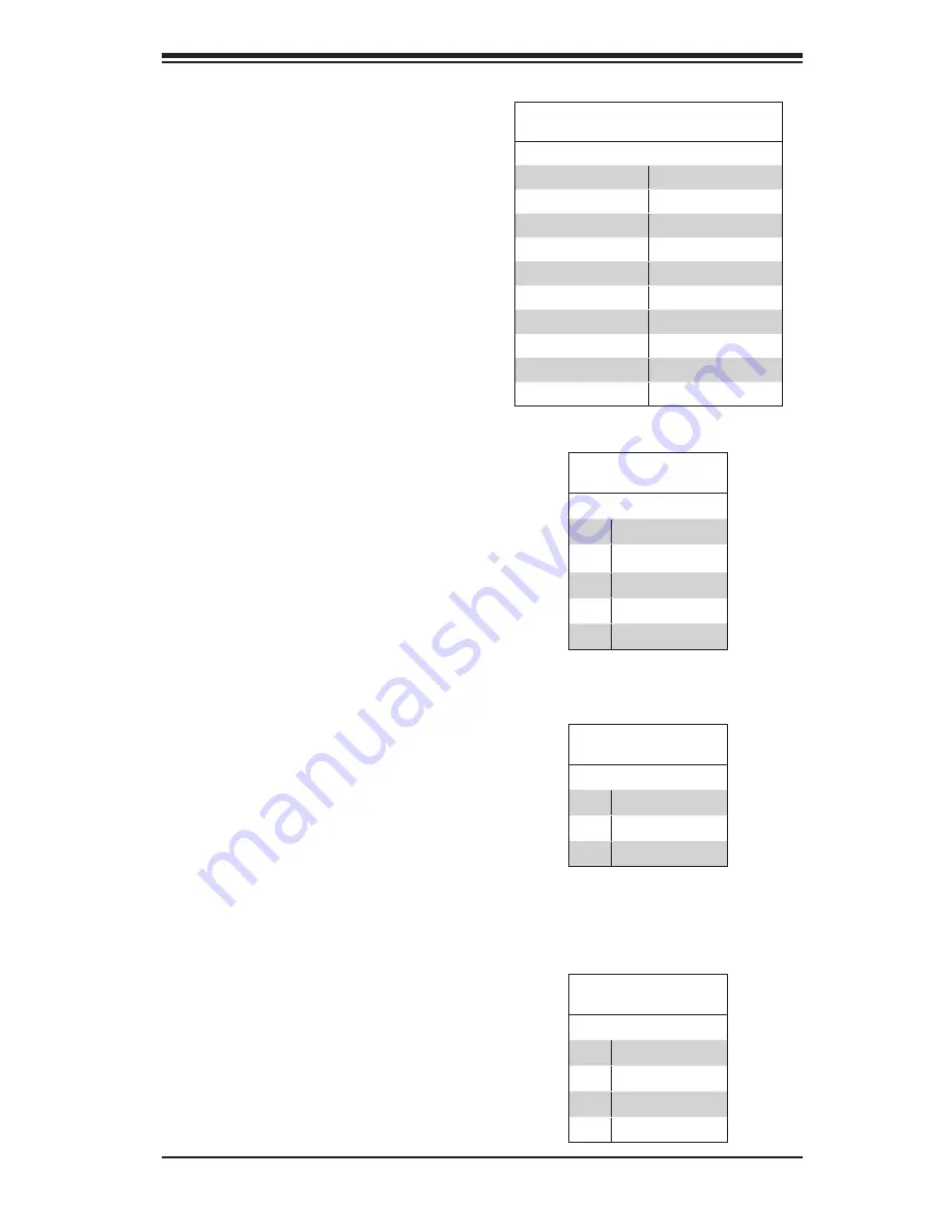
TPM Header/Port 80
A Trusted Platform Module/Port 80
header is located at JTPM1 to provide
TPM support and a Port 80 connec-
tion. Use this header to enhance
system performance and data secu-
rity. See the table on the right for pin
definitions.
TPM/Port 80 Header
Pin Definitions
Pin # Definition
Pin # Definition
1
LCLK
2
GND
3
LFRAME#
4
<(KEY)>
5
LRESET#
6
+5V (X)
7
LAD 3
8
LAD 2
9
+3.3V
10
LAD1
11
LAD0
12
GND
13
SMB_CLK4
14
SMB_DAT4
15
+3V_DUAL
16
SERIRQ
17
GND
18
CLKRUN# (X)
19
LPCPD#
20
LDRQ# (X)
PWR SMB
Pin Definitions
Pin# Definition
1
Clock
2
Data
3
PWR Fail
4
Ground
5
+3.3V
IPMB
A System Management Bus header
for IPMI 2.0 is located at JIPMB1.
Connect the appropriate cable here
to use the IPMB I
2
C connection on
your system.
IPMB Header
Pin Definitions
Pin# Definition
1
Data
2
Ground
3
Clock
4
No Connection
Summary of Contents for 1027R-73DARF
Page 1: ... SUPERSERVER 1027R 73DARF SUPER USER S MANUAL 1 0 ...
Page 5: ...Notes Preface v ...
Page 14: ...1 6 SUPERSERVER 1027R 73DARF User s Manual Notes ...
Page 24: ...2 10 SUPERSERVER 1027R 73DARF User s Manual Notes ...
Page 62: ...5 30 SUPERSERVER 1027R 73DARF User s Manual Notes ...
Page 104: ...A 2 SUPERSERVER 1027R 73DARF User s Manual Notes ...


