background image

B-3

Appendix B: System Specifi cations

Notes

Summary of Contents for 5037A-T

Page 1: ...SuperWorkstation 5037A T SUPER USER S MANUAL 1 0...

Page 2: ...ny such disputes Super Micro s total liability for all claims will not exceed the price paid for the hardware product FCC Statement This equipment has been tested and found to comply with the limits f...

Page 3: ...32D2 500B chassis Chapter 2 Server Installation This chapter describes the steps necessary to setup the SuperWorkstation 5037A T into a rack and check out the server configuration prior to powering up...

Page 4: ...ing the serverboard Chapter 6 Advanced Chassis Setup Refer to Chapter 6 for detailed information on the SC732D2 500B chassis You should follow the procedures given in this chapter when installing remo...

Page 5: ...v Preface Notes...

Page 6: ...m 1 3 1 4 Contacting Supermicro 1 5 Chapter 2 Installation 2 1 Overview 2 1 2 2 Unpacking the System 2 1 2 3 Accessing the Inside of the System 2 2 Chapter 3 System Interface 3 1 Overview 3 1 3 2 Cont...

Page 7: ...ing DIMMs 5 10 Memory Support 5 11 Memory Population Guidelines 5 11 5 6 Adding PCI Add On Cards 5 12 5 7 Motherboard Details 5 13 5 8 Connector Definitions 5 15 5 9 Jumper Settings 5 21 5 10 Onboard...

Page 8: ...BIOS Setup Utility 7 1 How To Change the Configuration Data 7 1 How to Start the Setup Utility 7 2 7 2 Main Setup 7 2 7 3 Advanced Setup Configurations 7 4 7 4 Security 7 19 7 5 Boot Configuration 7 2...

Page 9: ...on operating systems that have been certified for use with the SuperWorkstation 5037A T www supermicro com In addition to the motherboard and chassis various hardware components have been included wi...

Page 10: ...ors www supermicro com Memory The C7P67 has four DIMM slots that can support up to 32 GB of non ECC unbuf fered DDR3 1333 1066 SDRAM See Chapter 5 for details SATA A SATA controller is integrated into...

Page 11: ...nt Hard Drives The SC732D2 500B chassis was designed to support eight SATA hard drives Front Control Panel The control panel on the SuperWorkstation 5037A T includes system monitoring LEDs the main po...

Page 12: ...3 5 0GT s PCIe2 0_x1 PCIe x1 SLOT 5 5 0GT s PCIe2 0_x1 PCIe x1 SLOT 7 4 SATA II PORTS SATA II 300MB s 14 USB PORTS USB2 0 480Mbps 2 SATA III PORTS SATA III 600MB s 5 0GT s PCIe2 0_x1 Marvell 88SE9128...

Page 13: ...dress Super Micro Computer B V Het Sterrenbeeld 28 5215 ML s Hertogenbosch The Netherlands Tel 31 0 73 6400390 Fax 31 0 73 6416525 Email sales supermicro nl General Information support supermicro nl T...

Page 14: ...SuperWorkstation 5037A T User s Manual 1 6 Notes...

Page 15: ...if it was damaged in any way If the system itself shows damage you should file a damage claim with the carrier who delivered it Decide on a suitable location for the SuperWorkstation It should be situ...

Page 16: ...es two removable side covers allowing easy access to the chassis interior Removing the Side Covers 1 Disconnect the chassis from any power souce 2 Remove the two screws securing the left side cover to...

Page 17: ...nel Button A single push button is located on the front of the chassis Power 3 3 Communications Panel Components The SC732D2 features a front communication panel allowing easy access to the chassis co...

Page 18: ...LAN port s when flashing 3 4 Control Panel LEDs The control panel located on the front of the SC732 chassis has three LEDs These LEDs provide you with critical information related to different parts o...

Page 19: ...apter 5 This LED will remain flashing or on as long as the indicated condition exists 3 4 Drive Carrier LEDs Note the LEDs of some drive carriers may not function depending on the number of drives tha...

Page 20: ...3 4 SuperWorkstation 5037A T User s Manual Notes...

Page 21: ...should first power down the system with the operating system The unit has more than one power supply cord Disconnect both power supply cords before servicing to avoid electrical shock When working aro...

Page 22: ...into a cooling fan Remove any jewelry or metal objects from your body which are excellent metal conductors that can create short circuits and harm you if they come into contact with printed circuit bo...

Page 23: ...use Touch a grounded metal object before removing the board from the antistatic bag Do not let components or PCBs come into contact with your clothing which may retain a charge even if you are wearing...

Page 24: ...tice is not strictly followed Figure 4 1 Installing the Onboard Battery LITHIUM BATTERY BATTERY HOLDER Please handle used batteries carefully Do not damage the battery in any way a damaged battery may...

Page 25: ...er the center of the board to support it when handling The following measures are generally sufficient to protect your equipment from electric static discharge Precautions Use a grounded wrist strap d...

Page 26: ...age 5 9 for connector locations SATA drive data cable I SATA0 I SATA5 Control Panel cable JF1 Important Make sure the the cables do not come into contact with the fans Connecting Power Cables The C7P6...

Page 27: ...Port 0 2 USB 2 0 Port 9 12 USB 2 0 Port 1 3 Keyboard Mouse Port 13 LAN2 4 USB 2 0 Port 13 14 SPDIF Out 5 USB 2 0 Port 10 15 Surround Out 6 USB 2 0 Port 11 16 CEN LFE Out 7 USB 2 0 Port 12 17 Micropho...

Page 28: ...eatsink only Make sure to install the serverboard into the chassis before you install the CPU heatsinks When receiving a serverboard without a processor pre installed make sure that the plastic CPU so...

Page 29: ...CPU horizontally or vertically Do not rub the CPU against the surface or against any pins of the socket to avoid damage to the CPU or the socket With the CPU inside the socket inspect the four corner...

Page 30: ...ever locked into place Warning The CPU will only seat inside the socket in one direction Make sure it is properly inserted before closing the load plate If it doesn t close properly do not force it as...

Page 31: ...sest to the CPU fan power connector and are not interfered with other compo nents 3 Inspect the CPU Fan wires to make sure that the wires are routed through the bottom of the heatsink 4 Remove the thi...

Page 32: ...ing holes until you hear a click Also make sure to orient each fastener so that the narrow end of the groove is pointing outward 8 Repeat Step 7 to insert all four heatsink fasteners into the mounting...

Page 33: ...nd to prevent damage done to the CPU or other components Active Heatsink Removal 1 Unplug the power cord from the power supply 2 Disconnect the heatsink fan wires from the CPU fan header 3 Use your fi...

Page 34: ...DIMMs into the memory slots starting with DIMM 1A For best performance please use the memory modules of the same type and speed in the same bank See the DIMM Installation Chart on the following page 2...

Page 35: ...ry DIMM Slots per Channel DIMMs Populated per Channel DIMM Type POR Speeds Ranks per DIMM any combination 2 1 Unbuffered DDR3 1066 1333 Single Rank Dual Rank 2 2 Unbuffered DDR3 1066 1333 Single Rank...

Page 36: ...o the chassis The PCI slot shields protect the motherboard and its components from EMI and aid in proper ventilation so make sure there is always a shield covering each unused slot Possible System Mem...

Page 37: ...1A KB Mouse Rev 1 01 C7P67 J18 LAN CTRL LAN CTRL Audio CTRL Battery BIOS USB 3 0 CTRL Intel P67 PCH LGA1155 Marvel SATA 3 CTRL S I O 1394 CTRL PCI CTRL FP CTRL KB Mouse USB8 9 USB10 13 USB11 12 USB3 0...

Page 38: ...nnector Required KB Mouse Keyboard Mouse Connectors LAN1 LAN2 Gigabit RJ45 Ports LAN1 2 JSPDIF_In JSPDIF_OUT SPDIF_ Sony Philips Digital Interface _In SPDIF_Out Headers JTPM1 Trusted Platform Module T...

Page 39: ...the processor These power connectors meet the SSI EPS 12V specification See the tables on the right for pin definitions Required Connection 12V 8 pin Processor Power Pin Definitions JPW2 Pins Definiti...

Page 40: ...il LED Pin Definitions JF1 Pin Definition 7 Vcc Blue UID LED 8 OH Fan Fail LED OH Fan Fail Indicator Status State Definition Off Normal On Overheat Flash ing Fan Fail Power Button The Power Button con...

Page 41: ...ardware Monitoring section allows the BIOS to automatically set fan speeds based on the system tempera ture Refer to the table on the right for pin definitions Note Please use all 3 pin fans or all 4...

Page 42: ...ports 0 1 COM2 is located next to the IDE drive to provide ad ditional onboard serial connection support See the table on the right for pin definitions Serial Ports COM1 COM2 Pin Definitions Pin Defin...

Page 43: ...nitions JWOL Pin Definition 1 5V Standby 2 Ground 3 Wake up Wake On Ring The Wake On Ring header is located at JWOR This function allows your computer to wake up when receiving an incoming call to the...

Page 44: ...m temperature See the table on the right for pin definitions PWR Supply I2 C Pin Definitions SMB_PS Pin Definition 1 Clock 2 Data 3 PWR Fail 4 Ground S PDIF_Out Connector An S PDIF_Out connector is lo...

Page 45: ...2 1 3 2 1 CMOS Clear JBT1 is used to clear CMOS which will also clear any passwords Instead of pins this jumper consists of contact pads to prevent accidentally clearing the contents of CMOS To clear...

Page 46: ...94a Enable Disable Jumper Settings Both Jumpers Definition Pins 1 2 Enabled Pins 2 3 Disabled IEEE 1394a Enable JPI1 allows you to enable or disable the onboard IEEE 1394a support The default position...

Page 47: ...See the table on the right for more details Onboard PWR LED Indicator LE1 LED State Definition Off System Off On System On or System Off and Power Cable is Connected 5 11 SATA and IDE SATA Connection...

Page 48: ...2 Ground 3 Host Data 7 4 Host Data 8 5 Host Data 6 6 Host Data 9 7 Host Data 5 8 Host Data 10 9 Host Data 4 10 Host Data 11 11 Host Data 3 12 Host Data 12 13 Host Data 2 14 Host Data 13 15 Host Data...

Page 49: ...omputer icon and then on the icon representing your CD ROM drive Finally double click on the S Setup icon Figure 5 4 Driver Installation Display Screen Click the icons showing a hand writing on paper...

Page 50: ...crucial system information such as CPU temperature system voltages and fan status See the Figure below for a display of the SuperDoctor III interface Note The default User Name and Password for SuperD...

Page 51: ...Interface Display Screen Remote Control Note The SuperDoctor III program and User s Manual can be downloaded from the Supermicro web site at http www supermicro com products accessories software Supe...

Page 52: ...5 28 SuperWorkstation 5037A T User s Manual Notes...

Page 53: ...following measures are generally sufficient to protect your equipment from static discharge Precautions Use a grounded wrist strap designed to prevent static discharge Touch a grounded metal object be...

Page 54: ...ssis 3 Slide the left cover toward the rear of the chassis 4 Lift the left cover from the chassis 5 Remove the three screws securing the right side cover to the chassis 6 Slide the right cover toward...

Page 55: ...omponents in the chassis interior it is necessary to rotate the hard drive cage B This will provide sufficient room to install and configure the chassis components Rotating the Hard Drive Cage 1 Disco...

Page 56: ...isconnect the chassis from any power source 2 Rotate the hard drive cage outward 90 degrees as described in section 6 3 3 Disconnect all of the cables from the hard drive 4 Press the release tab on th...

Page 57: ...mmended for use in this chassis 8 Insert the new hard drive into the hard drive carrier 9 Insert the hard drive carrier into the hard drive cage sliding it towards the back of the the hard drive cage...

Page 58: ...6 6 SuperWorkstation 5037A T User s Manual Figure 6 5 Installing a Hard Drive Carrier into the Hard Drive Cage 1 11 1 9 Optional Screw...

Page 59: ...chassis must be powered down before hard drives can be removed from the hard drive carriers Removing and Installing 2 5 Hard Drives 1 Disconnect the chassis from any power source 2 Loosen the thumb s...

Page 60: ...er 7 Insert the new hard drive into the hard drive carrier 8 Insert the hard drive carrier into the hard drive cage sliding it towards the back of the the hard drive cage until it clicks into a locked...

Page 61: ...from the bottom and pulling off the front of the chassis 2 Remove the cover plate from the 3 5 device slot on the front of the chassis 3 Install the bracket rail A onto one side of the 3 5 device by...

Page 62: ...to the chassis 2 Insert the four rubber pins through mounting holes in the rear of the chassis and through the mounting holes in the rear fan 3 Pull the rubber pins through the mounting holes of the f...

Page 63: ...oles in the front fan 3 Pull the rubber pins through the mounting holes of the system fan to secure the fan to the chassis 4 Lower the fan into the chassis aligning the holes at the top of the front f...

Page 64: ...ezel Front Bezel Installation 1 Insert the tabs on the front bezel into the mounting holes on the front of the chassis 2 Ensure that the cover fits snugly This completes the installation of basic comp...

Page 65: ...Disconnect the motherboard cables 3 Remove the screws securing the power supply to the chassis which are located on the rear of the chassis Set these screws aside for later use 4 Gently lift the power...

Page 66: ...6 14 SuperWorkstation 5037A T User s Manual Notes...

Page 67: ...s that can be configured Grayed out options cannot be configured Options in blue can be configured by the user The right frame displays the key legend Above the key legend is an area reserved for a te...

Page 68: ...the BIOS do not shut down or reset the system while the BIOS is updating This is to avoid possible boot failure 7 2 Main Setup When you first enter the AMI BIOS Setup Utility you will enter the Main...

Page 69: ...ro C7P67 Version This item displays the BIOS revision used in your system Build Date This item displays the date when this BIOS was completed Processor The AMI BIOS will automatically display the stat...

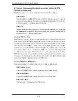
Page 70: ...wait until the F1 key is pressed if an error occurs The options are Disabled and Enabled Interrupt 19 Capture Interrupt 19 is the software interrupt that handles the boot disk function When this item...

Page 71: ...wer state before a power outage The options are Power On Power Off and Last State Processor Clock Options Warning Take Caution when changing the Advanced settings An incorrect value a very high DRAM f...

Page 72: ...un multiple operating systems and applications in independent partitions creating multiple virtual systems in one physical computer The options are Enabled and Disabled Note If there is any change to...

Page 73: ...s voltage and frequency This makes the processor more energy efficient resulting in further energy gains The options are HW_ALL SW_ALL and SW ANY CPU C3 Report Select Enabled for the CPU to report C3...

Page 74: ...Frequency This feature displays the status of based frequency of the system 1 Core Ratio Limit 2 Core Ratio Limit 3 Core Ratio Limit 4 Core Ratio Limit This increases multiplies a processor s core 1 c...

Page 75: ...latency performs better than those with higher latency The range of DRAM CAS latency is between 0 12ns and the step increment is 1ns The default setting is Auto DRAM RAS to CAS Delay tRCD This item d...

Page 76: ...1 050v 1 110v and the step increment is 0 010v The default setting is 1 050v PCH Voltage mv This item displays the status of the PCH voltage The range of the PCH volt age is between 1 050v 1 110v and...

Page 77: ...es If this item is set to Auto Legacy USB support will be automatically enabled if a legacy USB device is detected on the motherboard and vise versa The options are Disabled Enabled and Auto Port60h 6...

Page 78: ...This submenu allows the user to configure Onboard Chip settings USB 3 0 Legacy Support Select Enabled to support USB 3 0 Expansible_Host_Controller_Interface XHCI The options are Disabled and Enabled...

Page 79: ...ort5 The AMI BIOS will automatically display the status of a SATA port if a device is detected in the SATA port specified When the option AHCI Advanced Host Controller Interface Mode is select the fol...

Page 80: ...r of each PCI device installed on a PCI bus Select 64 to set the PCI latency to 64 PCI clock cycles The options are 32 64 96 128 160 192 224 and 248 Active State Power Management Select Enabled to ena...

Page 81: ...monitor Hardware Health of the system and review the status of each item when displayed Fan Speed Control Mode This feature allows the user to decide how the system controls the speeds of the onboard...

Page 82: ...OS Low This level is considered as the normal operating state The CPU temperature is well below the CPU Temperature Tolerance The motherboard fans and CPU will run normally as configured in the BIOS F...

Page 83: ...treams providing smooth playback and reducing the dependency on other timestamp calculation devices such as an x86 RDTSC In struction embedded in the CPU The High Precision Event Timer is used to repl...

Page 84: ...take precedence over other operations in the queue and be processed and executed immediately If the option Disable Take Ownership is selected the pending TPM operation will not take precedence over o...

Page 85: ...ight C XXXX American Megatrends Inc Set Setup Administrator Password Password Description If ONLY the administrator s password is set then this only limits access to Setup and is only asked for when e...

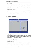
Page 86: ...Screen Select Item Enter Select Change Opt F1 General Help F2 Previous Values F3 Optimized Defaults F4 Save Exit ESC Exit Version x xx xxxx Copyright C XXXX American Megatrends Inc Setup Prompt Timeo...

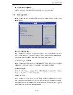
Page 87: ...ystem device Reset System with ME Disable Mode Save Changes and Exit After completing the system configuration changes select this feature and press Yes in the dialog box to save the changes you ve ma...

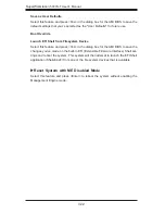
Page 88: ...m Device Select this feature and press Yes in the dialog box for the AMI BIOS to save the changes you ve made on the built in EFI Extensible Firmware Interface Shell set tings and reboot the system Th...

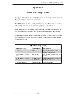
Page 89: ...oc curs you should consult with your system manufacturer for possible repairs These fatal errors are usually communicated through a series of audible beeps The numbers on the fatal error list corresp...

Page 90: ...A 2 SuperWorkstation 5037A T User s Manual Notes...

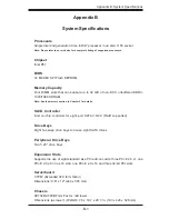
Page 91: ...e See the memory section in Chapter 5 for details SATA Controller Intel on chip controller for eight port SATA 3 0 2 0 RAID supported Drive Bays Eight hot swap drive bays to house eight SATA drives Pe...

Page 92: ...o 158 F Operating Relative Humidity 8 to 90 non condensing Non operating Relative Humidity 5 to 95 non condensing Regulatory Compliance Electromagnetic Emissions FCC Class B EN 55022 Class B EN 61000...

Page 93: ...B 3 Appendix B System Specifications Notes...

Page 94: ...erform be reasonably expected to result in significant injury or loss of life or catastrophic property damage Accordingly Supermicro dis claims any and all liability and should buyer use or sell such...

Reviews: