background image

B-2

S

uper

W

orkstation 7047A-73/7047A-T User's Manual

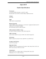
Chassis


SC743TQ-1200B-SQ Form Factor: tower/4U rackmount  


Dimensions (as tower): (WxHxD) 7 x 17.2 x 25.5 in. (178 x 437 x 648 mm)

Weight 


Gross (Bare Bone): 64 lbs. (29.1 kg.)

System Cooling 


Two (2) 8-cm low-noise chassis fans 


One (1) 9-cm low-noise exhaust fan 


Two (2) active CPU heatsinks

System Input Requirements 


AC Input Voltage: 100-240 VAC  


Rated Input Current: 8A (115V) to 12A (240V) 


Rated Input Frequency: 50-60 Hz

Power Supply


Rated Output Power: 1200W w/PFC (Part# PWS-1K25P-PQ) 


Rated Output Voltages: +3.3V (20A), +5V (20A), +12V (99A), -12V (0.3A), +5Vsb 
(3A) 


Power Supply Ef

fi

 ciency Rating: 94% (peak)

Operating 

Environment 


Operating Temperature: 10º to 35º C (50º to 95º F) 


Non-operating Temperature: -40º to 70º C (-40º to 158º F) 


Operating Relative Humidity: 8% to 90% (non-condensing) 


Non-operating Relative Humidity: 5 to 95% (non-condensing)

Regulatory Compliance 


Electromagnetic Emissions: FCC Class B, EN 55022 Class B, EN 61000-3-2/-
3-3, CISPR 22 Class B

Electromagnetic Immunity: EN 55024/CISPR 24, (EN 61000-4-2, EN 61000-4-3, 
EN 61000-4-4, EN 61000-4-5, EN 61000-4-6, EN 61000-4-8, EN 61000-4-11)
Safety: CSA/EN/IEC/UL 60950-1 Compliant, UL or CSA Listed (USA and 
Canada), CE Marking (Europe)

California Best Management Practices Regulations for Perchlorate Materials: 
This Perchlorate warning applies only to products containing CR (Manganese 
Dioxide) Lithium coin cells. “Perchlorate Material-special handling may apply. See 
www.dtsc.ca.gov/hazardouswaste/perchlorate”

Summary of Contents for 7047A-73

Page 1: ...SuperWorkstation 7047A 73 7047A T SUPER USER S MANUAL 1 0a...

Page 2: ...any such disputes Super Micro s total liability for all claims will not exceed the price paid for the hardware product FCC Statement This equipment has been tested and found to comply with the limits...

Page 3: ...klist of the main components included with the system and describes the main features of the X9DA7 and X9DAi serverboards and the SC743TQ 1200B SQ chassis Chapter 2 Server Installation This chapter de...

Page 4: ...ions headers and jumpers Refer to this chapter when adding or removing processors or main memory and when reconfig uring the serverboard Chapter 6 Advanced Chassis Setup Refer to Chapter 6 for detaile...

Page 5: ...v Preface Notes...

Page 6: ...em 1 3 1 4 Contacting Supermicro 1 5 Chapter 2 Installation 2 1 Overview 2 1 2 2 Unpacking the System 2 1 2 3 Preparing for Setup 2 1 Choosing a Setup Location 2 2 Rack Precautions 2 2 Server Precauti...

Page 7: ...Chapter 5 Advanced Serverboard Setup 5 1 Handling the Serverboard 5 1 Precautions 5 1 Unpacking 5 2 5 2 Serverboard Installation 5 2 5 3 Connecting Cables 5 3 Connecting Data Cables 5 3 Connecting Pow...

Page 8: ...g Chassis Cooling Fans 6 4 6 4 Drive Bay Installation 6 6 SAS SATA Backplane 6 7 Installing Components in the 5 25 Drive Bays 6 8 6 5 Power Supply 6 9 Power Supply Failure 6 9 Chapter 7 BIOS 7 1 Intro...

Page 9: ...73 7047A T www supermicro com In addition to the serverboard and chassis various hardware components have been included with the SuperWorkstation 7047A 73 7047A T as listed below Two 8 cm hot swap PWM...

Page 10: ...eight SAS2 ports The hot swap SAS drives are connected to a backplane that provides power bus termination and configuration settings Note The operating system you use must have RAID support to enable...

Page 11: ...SAS or SATA hard drives which are hot swappable units SAS is with 7047A 73 only Front Control Panel The control panel on the SuperWorkstation 7047A 73 7047A T provides you with system monitoring and...

Page 12: ...Type A PCI E x8 G3 PCI E X4 PCI E X1 PCI E X1 PCI E x16 G3 PCI E x8 G3 PCI E x16 G3 PCI E x8 G3 PCI E x16 G3 SLOT 3 1 4 1 3 1 2 1 1 2 1 3 8G DMI2 DMI2 DMI2 4GB s PCH C602J SSBD LANE1 2 3 4 LANE6 SCU...

Page 13: ...per Micro Computer B V Het Sterrenbeeld 28 5215 ML s Hertogenbosch The Netherlands Tel 31 0 73 6400390 Fax 31 0 73 6416525 Email sales supermicro nl General Information support supermicro nl Technical...

Page 14: ...SuperWorkstation 7047A 73 7047A T User s Manual 1 6 Notes...

Page 15: ...tem for the first time 2 2 Unpacking the System You should inspect the box the system was shipped in and note if it was damaged in any way If the system itself shows damage you should file a damage cl...

Page 16: ...ng on them In single rack installation stabilizers should be attached to the rack In multiple rack installations the racks should be coupled together Always make sure the rack is stable before extendi...

Page 17: ...ipment should be mounted into a rack so that the amount of airflow required for safe operation is not compromised Mechanical Loading Equipment should be mounted into a rack so that a hazardous conditi...

Page 18: ...e Sections of the Rack Rails The optional rackmount kit includes two rack rail assemblies Each of these as semblies consist of three sections an inner fixed chassis rail that secures to the chassis an...

Page 19: ...is rail sections you just removed along the side of the chassis making sure the screw holes line up Note that these two rails are left right specific Screw the rail securely to the side of the chassis...

Page 20: ...osition the fixed rack rail sliding rail guide assemblies at the desired location in the rack keeping the sliding rail guide facing the inside of the rack Screw the assembly securely to the rack using...

Page 21: ...irst keeping in mind that they are left right specific marked with L and R Then line up the rear of the chassis rails with the front of the rack rails Slide the chassis rails into the rack rails keepi...

Page 22: ...2 8 SuperWorkstation 7047A 73 7047A T User s Manual Notes...

Page 23: ...tatus of the system and the activity and health of specific components 3 2 Control Panel Buttons There are two push buttons located on the front of the chassis a power on off button and a reset button...

Page 24: ...ion you may need to take 1 2 Power Indicates power is being supplied to the system s power supply This LED should normally be on when the system is operating HDD This LED indicates SAS on the 7047A 73...

Page 25: ...ill increase its rpm to compensate but the power module should be replaced as soon as it s convenient 3 4 Drive Carrier LEDs Note the LEDs of some drive carriers may not function depending on the numb...

Page 26: ...3 4 SuperWorkstation 7047A 73 7047A T User s Manual Notes...
Page 27: ...you should first power down the system with the operating system The unit has more than one power supply cord Disconnect both power supply cords before servicing to avoid electrical shock When workin...

Page 28: ...or be pulled into a cooling fan Remove any jewelry or metal objects from your body which are excellent metal conductors that can create short circuits and harm you if they come into contact with prin...

Page 29: ...use Touch a grounded metal object before removing the board from the antistatic bag Do not let components or PCBs come into contact with your clothing which may retain a charge even if you are wearing...

Page 30: ...if this practice is not strictly followed Figure 4 1 Installing the Onboard Battery T UM ATT ATT O Please handle used batteries carefully Do not damage the battery in any way a damaged battery may rel...

Page 31: ...ant to handle them very carefully see previous chapter To prevent the serverboard from bending keep one hand under the center of the board to support it when handling The following measures are genera...

Page 32: ...the top cover of the chassis then pull the cover off 2 Make sure that the I O ports on the serverboard align properly with their respective holes in the I O shield at the back of the chassis 3 Carefu...

Page 33: ...7A 73 only SATA drive data cables I SATA0 I SATA3 ISAS SATA0 3 7047A T only Control Panel cable JF1 SGPIO cable T SGPIO1 T SGPIO2 7047A T only Important Make sure the the cables do not come into conta...

Page 34: ...Vcc Vcc Vcc Vcc Reset Button Power Button Ground x Key Power On LED HDD LED NIC1 LED NIC2 LED OH Fan Fail LED Power Fail LED Ground Ground 2 1 20 19 1 COM1 Port Turquoise 9 MIC In 2 USB 2 0 Port 0 10...

Page 35: ...o install the serverboard into the chassis before you install the CPU heatsinks When receiving a serverboard without a processor pre installed make sure that the plastic CPU socket cap is in place and...

Page 36: ...the WARNING plastic cap from the socket 5 Use your thumb and index finger to hold the CPU by its edges Align the CPU keys which are semi circle cutouts against the socket keys 6 Once they are aligned...

Page 37: ...gain and double check that the CPU is aligned properly 7 With the CPU in the socket in spect the four corners of the CPU to make sure that they are flush with the socket 8 Close the load plate Lock th...

Page 38: ...atsink on top of the CPU so that the four mounting holes are aligned with those on the serverboard and the heatsink bracket underneath 3 Screw in two diagonal screws i e the 1 and the 2 screws until j...

Page 39: ...e heatsink screws from the serverboard in the sequence as shown in the illustration below 2 Gently wriggle the heatsink to loosen it from the CPU Do not use excessive force when wriggling the heatsink...

Page 40: ...rt the desired number of DIMMs into the memory slots starting with P1 DIMM1A For best perfor mance please use the memory modules of the same type and speed in the same bank See the DIMM Installation C...

Page 41: ...en filled Processors and their Corresponding DIMM Slots CPU Corresponding DIMM Modules CPU 1 P1 A1 P1 B1 P1 C1 P1 D1 P1 A2 P1 B2 P1 C2 P1 D2 CPU 2 P2 E1 P2 F1 P2 G1 P4 H1 P2 E2 P2 F2 P2 G2 P2 H2 Proce...

Page 42: ...0 Platform Design Guide for memory population rules RDIMM Memory Support Ranks Per DIMM Data Width Memory Capacity Per DIMM Note 1 Speed MT s and Voltage Validated by Slot Per Channel SPC and DIMM Per...

Page 43: ...te DIMM capacity 2 Command Address Timing is 1N 3 Only 2Gb 4Gb DRAMs are supported and validated 4 The speeds listed are estimated only and will be verified through simulation 5 Please refer to the ES...

Page 44: ...ount of memory that remains available for operational use will be reduced when 4 GB of RAM is used The reduction in memory availability is disproportional See the following Memory Availability Table P...

Page 45: ...gin by removing the PCI slot shield for the slot you wish to populate 2 Fully seat the card into the card slot pushing down with your thumbs evenly on both sides of the card 3 Finish by using a screw...

Page 46: ...0 x16 CPU2 Slot2 PCI E 3 0 x4 in x8 TPM Port80 JF1 Always Populate DIMMxA First CPU2 S SATA3 I SATA1 COM1 USB3 0 0 1 S SATA0 P1 DIMMC2 P1 DIMMC1 JSPDIF_In JBT1 BIOS JD1 LAN1 2 USB2 0 0 1 2 3 JPWR2 J22...

Page 47: ...Slot5 PCI E 3 0 x16 CPU1 Slot3 PCI E 3 0 x16 CPU1 Slot2 PCI E 3 0 x4 in x8 CPU1 Slot1 PCI E 3 0 x16 TPM Port80 USB5 6 JF1 Always Populate DIMMxA First CPU2 I SATA5 I SATA4 I SATA3 I SATA2 I SATA1 COM1...

Page 48: ...io Connector BT1 Onboard Battery CNF1 CNF2 IEEE 1394a 1 2 Connectors COM1 Backplane COM Port1 FAN1 7 FANA CPU System Fan Headers Fan6 Fan7 CPU 1 2 Fans I SATA 0 5 LSI SATA Ports 0 5 SATA 0 1 SATA3 SAT...

Page 49: ...only SP1 Onboard Buzzer Internal Speaker STBY1 Standby Power Header T SGPIO 1 2 Serial Link General_Purpose IO Headers USB 2 0 0 1 2 3 Back Panel USB 2 0 Ports 0 1 2 3 USB 2 0 4 5 6 Front Panel Acces...

Page 50: ...ions JF1 Pin Definition 1 PW_ON 2 Ground Main ATX Power Supply Connector The main power supply connector J22 meets the SSI EPS 12V speci fication Refer to the table on the right for the pin definition...

Page 51: ...ections for the GB LAN port are on pins 11 and 12 of JF1 At tach an LED cable to display network activity See the table on the right for pin definitions OH Fan Fail Indicator Status State Definition O...

Page 52: ...4 PWM Control Power LED Speaker On JD1 header pins 1 3 are used for power LED indication and pins 4 7 are for the speaker See the tables on the right for pin definitions Please note that the speaker c...

Page 53: ...20 LDRQ X Standby Power Header The Standby Power header is located at STBY1 on the serverboard See the table on the right for pin definitions Standby Power Pin Definitions Pin Definition 1 5V Standby...

Page 54: ...in definitions 1394_1 Pin Definitions Pin Definition Pin Definition 1 PTPA0 2 PTPA0 3 GND 4 GND 5 PTPB0 6 PTPB0 7 PWR 1394a 8 PWR 1394a 10 Shield GND 1394_2 Pin Definitions Pin Definition Pin Definiti...

Page 55: ...audio support You will also need to have a cable to use each connection SPDIF_In Pin Definitions Pin Definition 1 S PDIF_In 2 Ground SIMBMC Slot The SIM_BMC Baseboard Manage ment Control slot is locat...

Page 56: ...the jumper is on both pins and Open means the jumper is either on only one pin or completely removed Connector Pins Jumper Setting 3 2 1 3 2 1 CMOS Clear JBT1 is used to clear CMOS which will also cl...

Page 57: ...application that hangs See the table on the right for jumper settings Watch Dog must also be enabled in BIOS Watch Dog Jumper Settings Jumper Setting Definition Pins 1 2 Reset default Pins 2 3 NMI Op...

Page 58: ...n jumpers JPP0 JPP1 allow the user to configure JTAG scan settings for system debugging See the table on the right for jumper settings JTAG Scan JPP0 Jumper Settings Jumper Setting Definition Pins 1 2...

Page 59: ...ED Connection Speed Indicator LED Color Definition Off No Connection or 10 Mb s Green 100 Mb s Amber 1 Gb s Onboard Power LED An Onboard Power LED is located at LE1 on the serverboard When this LED is...

Page 60: ...hite and four SATA2 Ports I SATA2 5 are located on the serverboard These ports provide serial link signal connections which are faster than the connections of Parallel ATA See the table on the right f...

Page 61: ...ed with your serverboard Driver Tool Installation Display Screen Note Click the icons showing a hand writing on paper to view the readme files for each item Click the computer icons to the right of th...

Page 62: ...nvironment and operations of your system SuperDoctor III displays crucial system information such as CPU temperature system voltages and fan status See the Figure below for a display of the SuperDocto...

Page 63: ...Interface Display Screen Remote Control Note The SuperDoctor III program and User s Manual can be downloaded from the Supermicro web site at http www supermicro com products accessories software Supe...

Page 64: ...5 34 SuperWorkstation 7047A 73 7047A T User s Manual Notes...

Page 65: ...he following measures are generally sufficient to protect your equipment from static discharge Precautions Use a grounded wrist strap designed to prevent static discharge Touch a grounded metal object...

Page 66: ...6 2 SuperWorkstation 7047A 73 7047A T User s Manual 8 SAS SATA Drive Bays behind locking bezel Figure 6 1 Chassis Front View System Reset Main Power 5 25 Drive Bays 2 USB Ports...

Page 67: ...s on the control panel inform you of system status see Figure 6 2 for details See Chapter 5 for details on JF1 Figure 6 2 Front Control Panel LEDs Power NIC1 HDD Overheat Fan Fail Indicates power is b...

Page 68: ...s the exhaust fan and the power supply fans run continuously The chassis fans are hot pluggable and can be replaced without powering down the system Replacing Chassis Cooling Fans Removing a Fan 1 Fir...

Page 69: ...Chapter 6 Advanced Chassis Setup 6 5 Figure 6 3 Removing a Chassis Fan...

Page 70: ...rier 2 Secure the drive to the carrier with four screws see Figure 6 5 6 4 Drive Bay Installation A total of six SAS or SATA drives may be housed in the SC743TQ 1200B SQ chas sis The drive IDs are pre...

Page 71: ...h any metal objects and make sure no ribbon cables touch the backplane or obstruct the airflow holes Figure 6 4 Removing a SAS SATA Drive Carrier SAS SATA Backplane The SAS SATA drives plug into a dri...

Page 72: ...ents 3 With the cover off remove the screws that secure the drive carrier to the chassis one side only then push the entire empty drive carrier out from the back Adding a DVD CD ROM Drive 1 Remove the...

Page 73: ...directly from Supermicro As there is only one power supply unit the system must be pow ered down before removing and or replacing the power supply for whatever reason Replacing the Power Supply 1 Firs...

Page 74: ...6 10 SuperWorkstation 7047A 73 7047A T User s Manual Notes...

Page 75: ...plays all the options that can be configured Grayed out options cannot be configured Options in blue can be configured by the user The right frame displays the key legend Above the key legend is an ar...

Page 76: ...less your system has a BIOS related issue Flashing the wrong BIOS can cause irreparable damage to the sys tem In no event shall the manufacturer be liable for direct indirect special incidental or con...

Page 77: ...Tab key to move between fields The date must be entered in Day MM DD YY format The time is entered in HH MM SS format Note The time is in the 24 hour format For example 5 30 P M appears as 17 30 00 X...

Page 78: ...ay mode set by the system BIOS The options are Force BIOS and Keep Current Bootup Num Lock Use this feature to set the Power on state for the Numlock key The options are Off and On Wait For F1 If Erro...

Page 79: ...Seconds Override the system will power off when the user presses the power button for 4 seconds or longer The options are Instant Off and 4 Seconds Override Restore on AC Power Loss Use this feature t...

Page 80: ...Intel s website for more information The options are All 1 2 4 and 6 Limit CPUID Maximum This feature allows the user to set the maximum CPU ID value Enable this function to boot the legacy operating...

Page 81: ...support Data Cache Unite DCU prefetch to speed up data accessing and processing in the DCU to enhance CPU performance The options are Disabled and Enabled DCU IP Prefetcher Select Enabled for DCU Data...

Page 82: ...etailed information The options are Disabled and Enabled Turbo Mode This feature allows processor cores to run faster than marked frequency in specific conditions The options are Disabled and Enabled...

Page 83: ...nced Performance Balanced Energy and Energy Efficient Factory Long Duration Power Limit This item displays the power limit set by the manufacturer during which long duration power is maintained Long D...

Page 84: ...ng the system resource for other tasks The options are Disabled and Enabled DCA Support Select Enabled to use Intel s DCA Direct Cache Access Technology to improve data transfer efficiency The options...

Page 85: ...OU3 PCIe Port If this feature allows the user to set the bus speed between the IOU3 and the PCI Exp port The options are x4x4x4x4 x4x4x8 x8x4x4 x8x8 and x16 The default for IOH 0 is x16 The default fo...

Page 86: ...layed as detected by the BIOS Memory Mode When Independent is selected all DIMMs are available to the operating system When Mirroring is selected the motherboard maintains two identical copies of all...

Page 87: ...s are Disabled and Enabled DDR Speed Use this feature to force a DDR3 memory module to run at a frequency other than what the system is specified in the specification The options are Auto Force DDR3 8...

Page 88: ...AM module is in operation The options are Disabled Mode 0 and Mode 1 Device Tagging Select Enabled to support device tagging The options are Disabled and En abled Thermal Throttling Throttling improve...

Page 89: ...nterface applications only The settings are Disabled Enabled and Auto Port 60 64 Emulation Select Enabled to enable I O port 60h 64h emulation support for the legacy USB keyboard so that it can be ful...

Page 90: ...controller and set the compatibility mode The options are Enhanced and Compatible The default for SATA controller 0 is Compatible The default for SATA control ler 1 is Enhanced AHCI Mode The followin...

Page 91: ...ions are Disabled and Enabled XPCIe PCI PnP Configuration PCI ROM Priority Use this feature to select the Option ROM to boot the system when there are mul tiple Option ROMs available in the system The...

Page 92: ...w the system BIOS to automatically set the ASPM level for the system Select Disabled to disable ASPM support The options are Disabled Force L0 and Auto Warning Enabling ASPM support may cause some PCI...

Page 93: ...ing is Auto which will allow the AMI BIOS to automatically select the best setting for the PECI platform P S 2 Connector This option enables the selection of keyboard or mouse for the PS 2 connector T...

Page 94: ...detect data transmission errors Select Even if the parity bit is set to 0 and the number of 1 s in data bits is even Select Odd if the parity bit is set to 0 and the number of 1 s in data bits is odd...

Page 95: ...r to configure the following Console Redirection settings to support Out of Band Serial Port management Console Redirection Select Enabled to use a COM Port selected by the user for Console Redirectio...

Page 96: ...er saving Select Full Speed for the fan to run at the full speed which will increase power consumption The options are Standard Full Speed and Optimal CPU Temperature Display Mode This feature display...

Page 97: ...the BIOS Voltage Readings The following voltage readings will be displayed VTT 1 1V 1 5V 5VSB 5V 12V CPU1 Vcore CPU2 Vcore VDIMM AB VDIMM CD VDIMM EF VDIMM GH 3 3V 3 3VSB and VBAT XACPI Setting Use th...

Page 98: ...Available if a TPM device is installed TPM Support Select Enabled on this item and enable the TPM jumper on the motherboard to allow TPM support to improve data integrity and network security The opt...

Page 99: ...d Memory Correctable Error Threshold This feature allows the user to enter the threshold value for correctable memory errors The default setting is 10 PCI Error Logging Support Select Enabled to suppo...

Page 100: ...ptions are Do Nothing and Erase Immediately SMBIOS Event Log Standard Settings Log System Boot Event Select Enabled to log system boot events The options are Disabled and Enabled MECI Multiple Event C...

Page 101: ...Boot Option This feature allows the user to delete a previously defined boot device from which the system boots during startup Select Screen Select Item Enter Select Change Opt F1 General Help F2 Prev...

Page 102: ...cters to 20 characters long Select Screen Select Item Enter Select Change Opt F1 General Help F2 PreviousValues F3 Optimized Defaults F4 Save Exit ESC Exit Version 2 14 1219 Copyright C 2011 American...

Page 103: ...ng you if you want to exit the BIOS setup without sav ing click Yes to quit BIOS without saving the changes or click No to quit the BIOS and save changes Save Options Save Changes Select this option a...

Page 104: ...zed defaults Save as User Defaults Select this feature and press Enter to save the current settings as the user s defaults When the dialog box appears asking you if you want to save values as user s d...

Page 105: ...curs you should consult with your system manufacturer for possible repairs These fatal errors are usually communicated through a series of audible beeps The numbers on the fatal error list correspond...

Page 106: ...A 2 SuperWorkstation 7047A 73 7047A T User s Manual Notes...

Page 107: ...DIMMs Note See the memory section in Chapter 5 for details SAS Controller 7047A 73 only LSI 2308 controller for eight port SAS RAID supported SATA Controller Intel on chip controller for six port SATA...

Page 108: ...Environment Operating Temperature 10 to 35 C 50 to 95 F Non operating Temperature 40 to 70 C 40 to 158 F Operating Relative Humidity 8 to 90 non condensing Non operating Relative Humidity 5 to 95 non...

Page 109: ...B 3 Appendix B System Specifications Notes...

Page 110: ...to perform be reasonably expected to result in significant injury or loss of life or catastrophic property damage Accordingly Supermicro dis claims any and all liability and should buyer use or sell...

Reviews: