Chapter 5: Advanced Serverboard Setup
5-21
CMOS Clear
JBT1 is used to clear CMOS and will also clear any passwords. Instead of pins,
this jumper consists of contact pads to prevent accidentally clearing the contents
of
CMOS.
To clear CMOS,
1) First power down the system and unplug the power cord(s).
2) With the power disconnected, short the CMOS pads with a metal object such as
a small screwdriver for at least four seconds.
3) Remove the screwdriver (or shorting device).
4) Reconnect the power cord(s) and power on the system.
Notes:
Do not use the PW_ON connector to clear CMOS.
The onboard battery does not need to be removed when clearing CMOS, however
you must short JBT1 for at least four seconds.
JBT1 contact pads
3rd Power Supply Fail Detect
Enable/Disable
The system can notify you in the event
of a power supply failure. This feature
assumes that three redundant power
supply units are installed in the chas-
sis. If you only have one or two power
supplies installed, you should disable
the function with the J3P header to pre-
vent false alarms. See the table on the
right for jumper settings.
3rd Power Supply Fail Signal
Jumper Settings (J3P)
Jumper Setting Defi nition
Open
Disabled
Closed
Enabled
VGA Enable/Disable
JPG1 allows you to enable or disable
the VGA port. The default position
is on pins 1 and 2 to enable VGA.
See the table on the right for jumper
settings.
VGA Enable/Disable
Jumper Settings (JPG1)
Jumper Setting Defi nition
Pins 1-2
Enabled
Pins 2-3
Disabled
Summary of Contents for AS1021M-T2R
Page 1: ...AS1021M T2R USER S MANUAL 1 0a SUPER ...
Page 5: ...v Preface Notes ...
Page 10: ...Notes x AS1021M T2R User s Manual ...
Page 25: ...Chapter 2 Server Installation 2 9 Figure 2 5 Accessing the Inside of the System ...
Page 30: ...3 4 AS1021M T2R User s Manual Notes ...
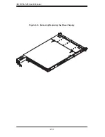
Page 70: ...6 10 AS1021M T2R User s Manual Figure 6 6 Removing Replacing the Power Supply ...
Page 90: ...A 2 AS1021M T2R User s Manual Notes ...


