C-5
Appendix C: SAS-213A Backplane Specifications
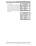
11. - 12. ACT_IN:
The activity LED connectors, designated JP26,
and JP27 are used to indicate the activity
status of each SAS drive. The activity LED
connector is located on the front panel. For
the activity LED connector to work properly,
connect using a 10-pin LED cable. This is only
used when the activity LED is not supported by
the hard drive.
SAS Activity LED Header
Pin Definitions
Pin# Definition Pin# Definition
1
ACT IN#0
6
ACT IN#4
2
ACT IN#1
7
ACT IN#5
3
ACT IN#2
8
ACT IN#6
4
ACT IN#3
9
ACT IN#7
5
Ground
X
Empty
SAS Activity LED Header
Pin Definitions
Pin# Definition Pin# Definition
1
ACT IN#8
6
ACT IN#12
2
ACT IN#9
7
ACT IN#13
3
ACT IN#10
8
ACT IN#14
4
ACT IN#11
9
ACT IN#15
5
Ground
X
Empty
Summary of Contents for SC219 Chassis Series
Page 8: ...SC219 Chassis Manual viii Notes ...
Page 12: ...SC219 Chassis Manual 1 4 Notes ...
Page 40: ...SC219 Chassis Manual 4 20 Notes ...
Page 50: ...SC219 Chassis Manual 5 10 Notes ...
Page 54: ...SC219 Chassis Manual A 4 Notes ...
Page 56: ...SC219 Chassis Manual B 2 Notes ...
Page 67: ...C 11 Appendix C SAS 213A Backplane Specifications Notes ...


