4-9
Chapter 4: Chassis Setup and Maintenance
A
1
B
C
D
E
F
G
H
I
J
K
L
M
2
3
4
5
6
7
8
9
10
DESIGN / ³]-p :
MODEL NO./ ¾÷«¬ :
SIZE/¹Ï®Ø
APPROVED / ¼f®Ö :
DRAWN / ø¹Ï :
MATERIAL / §÷½è :
UNIT / ³æ¦ì :
FINISH / ªí-±³B¸Ì :
DATE / ¤é´Á:
DATE / ¤é´Á:
DATE / ¤é´Á:
TITLE / «~¦W :
PART NO. / ®Æ¸¹ :
Ablecom Technology Inc.
A
BLEC
DWG NO. / ¹Ï¸¹ :
¤j˚T¬ì§ÞªÑ¥÷¦³--¤½¥q
THE 3RD PROJECTION
²Ä¤T¨¤ªk
M
R E V I S I O N S / -×-q
REV
ª©¥»
DESCRIPTION
±Ô-z
LOCATION
¦ì¸m
DRAWN
-קïªÌ
DATE
¤é´Á
SC502_SYSTEM_ASSY
A0
*
SCALE / ¤ñ¨Ò :
1:1
SHEET
1
OF
1
SC502
*
SHO
29-Nov-07
See Note.
SHO
29-Nov-07
MM
*
REV.
ª©¥»
1
RANGE
½d³ò
TOLERANCE
¤½®t
X.xx
± 0.10
X.x
± 0.25
X
± 1.00
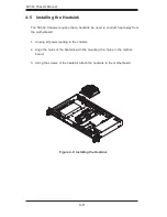
Figure 4-10: Installing an Active Heatsink
Note:
Intel Celeron 400 35W platform motherboards may require an optimized design
(SNK-P0032A4) active heatsink. Refer to Appendix A of this manual for basic
heatsink information. Refer to your motherboard documentation for detailed heatsink
information and installation instructions, specific to your motherboard.
Checking the Server's Air Flow
Make sure there are no objects to obstruct airflow in and out of the server.
Use only recommended server parts.
Make sure no wires or foreign objects obstruct air flow through the chassis.
Pull all excess cabling out of the airflow path, or use shorter cables.
The control panel LEDs inform you of system status. See “Chapter 3: System
Interface” for details on the LEDs and the control panel buttons.
1.
2.
3.
4.
Summary of Contents for SC502 Series
Page 10: ...SC502 Chassis Manual 1 4 Notes ...
Page 28: ...SC502 Chassis Manual 4 12 Notes ...
Page 34: ...SC502 Chassis Manual 5 6 Notes ...

