SC743 Chassis Manual
D-4
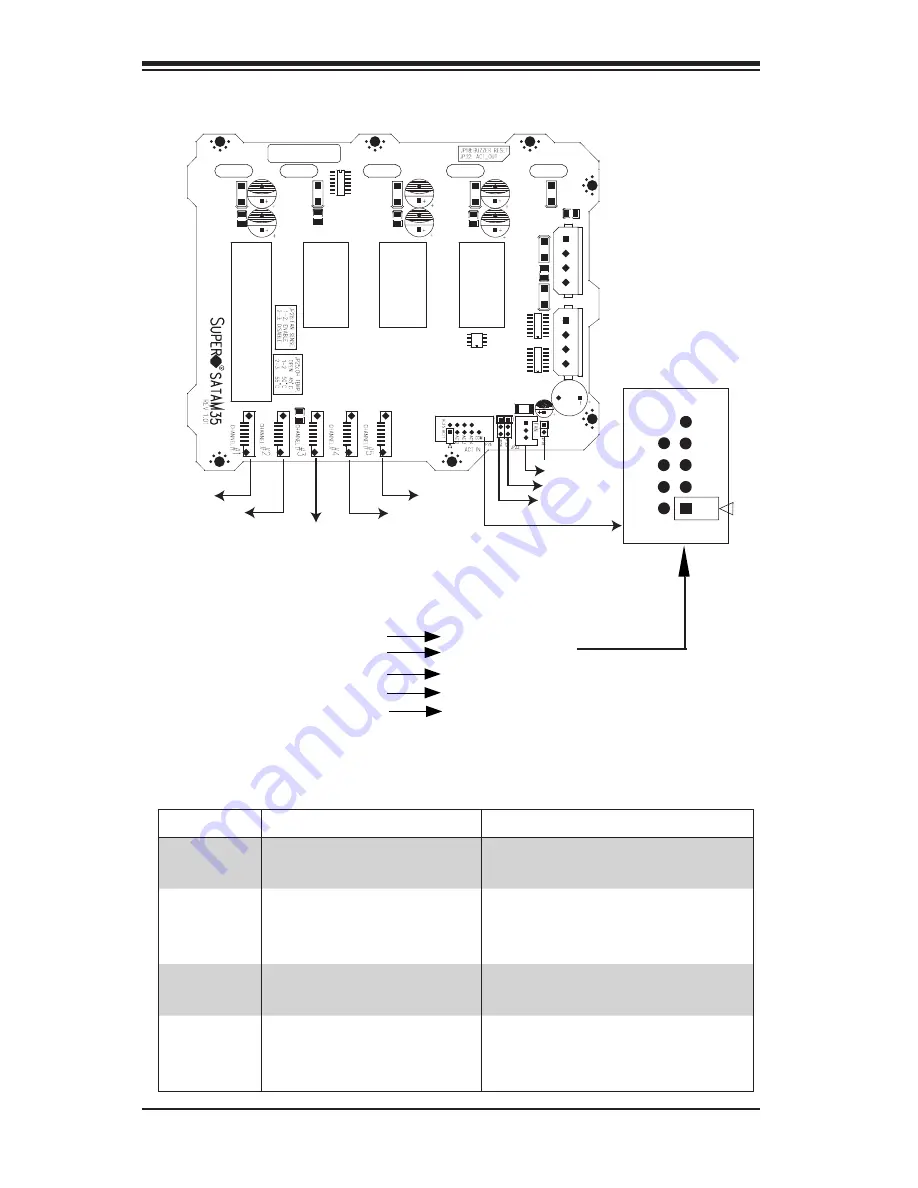
Jumper Settings for the CSE-M35T1 (SATA) Mobile Rack
Location of Jumpers
Key
JP26
Activity LEDs-
Pin Definitions
Act. LED 1
Act. LED 2
Act. LED 3
Act. LED 4
Act. LED 5
Channel 1
Channel 2
Channel 3
Channel 4
Channel 5
Figure D-2: Jumper Locations (SATA)
JP28
JP25
JP18
Channel #1
Channel #2
ACT5
FAN
Channel #3
Channel #4
Channel #5
ACT6
ACT7
ACT8
ACT1
ACT2
ACT3
ACT4
COM
Pin 1
Pin 1
Jumper
Description
Setting
JP18
Buzzer Reset
Closed: Enable
Open: Disable (Default)
JP25
Overheat Temperature
Open: 45
o
C
1-2: 50
o
C (Default)
2-3: 55
o
C
JP26
Act#1-Act#5
Connect this header to
CBL0057 (SATA LED cable)
JP28
Fan Sense
1-1 Enabled (if a fan is not
present, the alarm will sound)
(Default) 2-3: Disabled
Summary of Contents for SC743i-465
Page 20: ...SC743 Chassis Manual 3 6 Notes...
Page 40: ...SC743 Chassis Manual 4 20 Notes...
Page 54: ...SC743 Chassis Manual B 4 Notes...
Page 64: ...SC743 Chassis Manual C 10 Notes...
Page 74: ...SC743 Chassis Manual D 10 Notes...
Page 93: ...F 9 Appendix F SATA 743 Backplane Specifications Notes...


