SC825 Chassis Manual
5-12
5-13
Chapter 5: Chassis Setup and Maintenance
PCI Slot Setup for SC825U (Universal Output) and
SC825W
SC825U and SC825W chassis accepts a slightly smaller "L" shaped motherboard to
allow for a universal expansion card. This universal output card allows the systems
to accept SAS, SCSI, IB, Ethernet, and other types of connections.
SC825U/SC825W chassis are setup similar to 825RC chassis with two differences:
A. The SC825U/SC825W chassis accepts three full-length, full-height expansion
cards instead of four. The fourth slot is used for the UI/O card (SC825U) or a 4x
full-height, full-length card (SC825W).
B. The SC825U/SC825W chassis includes a bracket that extends from the fan row
to the back of the chassis. This bracket provides support for the riser card.
Installing a Universal Input/Output Card in the SC825U chassis:
1. Power down the system and remove the power cords from the rear of the
power supply. Open the chassis cover as described in Section 5-3.
2. Connect the universal input/output to the motherboard using the slots pro-
vided on the motherboard and the back panel.
3. Secure the card to the chassis using the four screws provided with the chas-
sis packaging.
The SC825U chassis accepts 3 full-height/full-length slots and 3 low profile slots.
Installing Add-on Cards in the SC825U and SC825W Chassis
1.
Disconnect the power supply, lay the chassis on a flat surface, and open the
chassis cover.
2. If you are using a universal input/output card, make sure it is installed before
continuing (applies only to the SC825U).
3.
If you installing low profile expansion cards, remove the chassis air shroud.
4. Secure the card to the chassis using the four screws provided with the chas-
sis packaging.
5-8 Installing the Air Shroud
Air shrouds concentrate airflow to maximize fan efficiency. The SC825 chassis air
shroud does not require screws to set up.
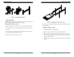
Figure 5-12. Air Shroud for SC825LP Chassis
Installing the Air Shroud
1.
Confirm that your air shroud matches your chassis model. Each shroud is
labeled SC825LP or SC825U,
2. Power down the system and remove the power cords from the rear of the
power supply. Open the chassis cover as described in Section 5-3.
3.
Place air shroud in the chassis. The air shroud fits behind the two fans clos
-
est to the power supply.
Note that if a 16 DIMM (13.68" x 13") motherboard is used, it is necessary to use
the optional MCP-310-82502-0N air shroud. For ordering information, visit the
Supermicro website at www.supermicro.com and click on the Where to Buy link.
Summary of Contents for SC825TQ-560LP
Page 5: ...SC825 Chassis Manual viii Notes...
Page 9: ...SC825 Chassis Manual 1 6 Notes...
Page 20: ...2 20 SC825 Chassis Manual Notes...
Page 37: ...SC825 Chassis Manual 5 22 Notes...
Page 42: ...SC825 Chassis Manual 6 8 Notes...
Page 46: ...SC825 Chassis Manual A 6 Notes...


