C-5
Appendix C: Backplane
JF4
58
59
53
1
2
54
62
55
28
27
JF3
58
59
53
1
2
54
62
55
28
27
JF2
58
59
53
1
2
54
62
55
28
27
JF1
58
59
53
1
2
54
62
55
28
27
16
33
48
49
64
32
33
48
49
U21
JF6
16
JF5
16
1
11
12
22
23
34
44
U6
1
4
J21
1
JP36
1
JP35
JPI2C1
1
5
JPW3
5
4
8
JPW2
1
5
4
8
JPW1
12
13
1
F16
Y2
X1
4
1
JP55
1
JP54
4
1
JP57
4
1
JP56
DESIGNED IN USA
F23
F24
F25
F26
F36
C121
C269
+
+
C200
+
C203
+
C119
+
C197
+
C198
+
C201
+
C3
+
C44
+
C45
+
C84
+
C85
C
A
D1
R128
R132
JP71
JP70
JP69
BAR CODE
UPGRADE#B
HB
UPGRADE#A
JF6-B
JF5-A
MB-B
MB-A
1
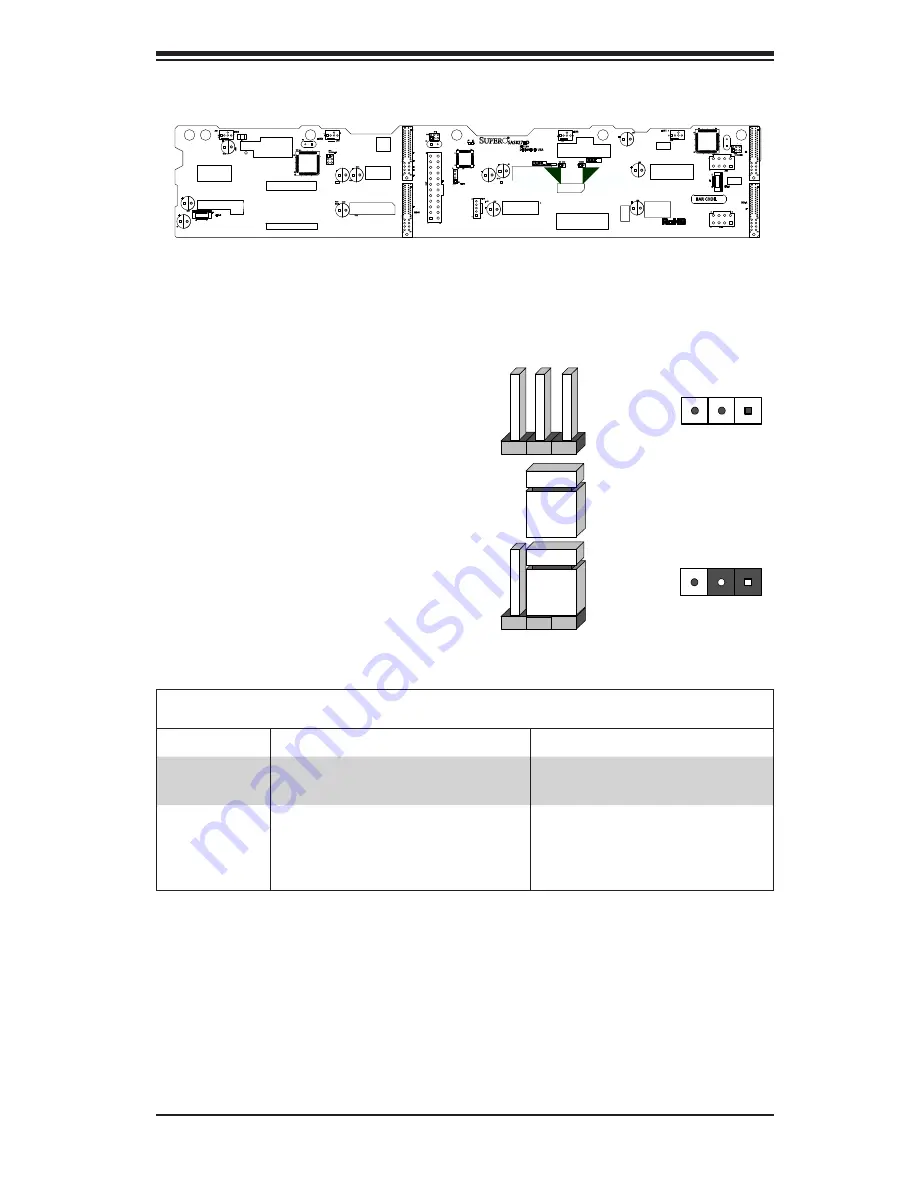
JP36:
OPEN:DEFAULT
CLOSE:ANY POWER BUTTON
JP35:
OPEN:DEFAULT
CLOSE:LED TEST
TO PS
SPI
DEBUG
FAN4
FAN3
FAN2
FAN1
REV 1.00
SAS827HD
JP35
JP36
Explanation of Jumpers
To modify the operation of the backplane,
jumpers can be used to choose between
optional settings. Jumpers create shorts
between two pins to change the function
of the connector. Pin 1 is identified with
a square solder pad on the printed circuit
board.
Note:
On two pin jumpers, "Closed"
means the jumper is on and "Open" means
the jumper is off the pins.
Connector
Pins
Jumper
Setting
3 2 1
3 2 1
Jumper Settings
Jumper
Jumper Settings
Notes
JP35
Open: Default
Closed: LED test
LED test
JP36
Open: Default, multiple power but-
ton functionality
Closed: Single power button
functionality
Any power button
Figure C-3. Front Jumpers
Summary of Contents for SC827HD-R1400B
Page 1: ...SC827HD Chassis Series USER S MANUAL 1 0 SUPER SC827HD R1400B SC827HD R1620B...
Page 12: ...SC827HD Chassis Manual 1 4 Notes...
Page 32: ...2 20 SC827HD Chasssis Manual Notes...
Page 38: ...SC827HD Chassis Manual 4 4 Notes...
Page 68: ...SC827HD Chassis Manual 6 10 Notes...
Page 70: ...SC827HD Chassis Manual A 2 Notes...
Page 72: ...SC827HD Chassis Manual B 2 Notes...
Page 81: ...C 9 Appendix C Backplane Notes...


