2-
4
Pow
er C
ont
r
ol
C
a
rd User
'
s
Gu
ide
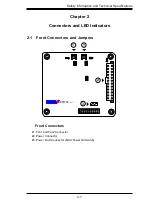
Front Pane LEDs
LED
STATE
SPECIFICATION
Pow
er LE
D
O
N
A
ct
i
v
i
ty
i
n Pow
er C
ont
r
ol
B
oa
rd
Fan
1
Fa
i
l
O
N
Fa
i
lu
re i
n Fan
1
Fan
2
Fa
i
l
O
N
Fa
i
lu
re i
n Fan
2
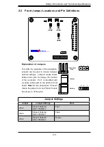
2-4 LED Indicators
A
A
A
A
A
A
REV 1.00
JBPWR2
Power LED
Fan2 Fail
Fan1 Fail
2-5 Power Card Placement
Front Processor
Locations
Secure the Board to
these four holes
Summary of Contents for SC836E1-R800B
Page 1: ...SC836 CHASSIS Series SC836TQ R800V B SC836E1 R800V B SC836E2 R800V B USER S MANUAL 1 0d SUPER...
Page 4: ...SC836 Chassis Manual iv Notes...
Page 10: ...SC836 Chassis Manual x Notes...
Page 14: ...SC836 Chassis Manual 1 4 Notes...
Page 54: ...SC836 Chassis Manual 7 8 Notes...
Page 56: ...Appendices 2 Notes...
Page 64: ...SC836 Chassis Manual B 2 Notes...
Page 70: ...1 2 Backplane User s Guide Notes...
Page 74: ...2 4 Backplane User s Guide Notes...
Page 98: ...i SAS 836TQ Backplane User s Guide Notes...
Page 100: ...1 2 SAS 836TQ Backplane User s Guide Notes...
Page 112: ...2 12 SAS 836TQ Backplane User s Guide Notes...
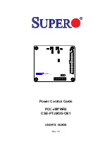
Page 113: ...Rev 1 0 Power Control Cards PCC JBPWR2 CSE PTJBOD CB1 USER S GUIDE A A A A A A REV 1 00 JBPWR2...


