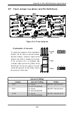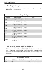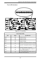
D-4
SC847 Chassis Manual
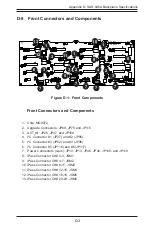
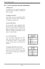
D-6 Front Connector and Pin Definitions
1. MG9072 Chip
The MG9072 is an enclosure management
chip that supports the SES-2 controller and
SES-2 protocols.
2. Upgrade Connectors
The upgrade connectors are designated JP69,
JP78, and JP115 and are used for manufactur-
er's diagnostic purposes only.
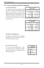
3. Activity LED Header
The activity LED header, designated JP26,
JP47 and JP108, is used to indicate the activ-
ity status of each SAS drive. The Activity LED
Header is located on the front panel. For the
Activity LED Header to work properly, connect
using a 10-pin LED cable.
4., 5., 6. I
2
C Connectors
The I
2
C Connectors, designated JP37, JP95,
JP52, JP96, JP116, and JP117, are used
to communicate to HDD to support SES-2
protocol. See the table on the right for pin
definitions.
I
2
C Connector
Pin Definitions
Pin# Definition
1
Data
2
Ground
3
Clock
4
No Connection
Backplane
Main Power
4-Pin Connector
Pin# Definition
1
+12V
2 and 3
Ground
4
+5V
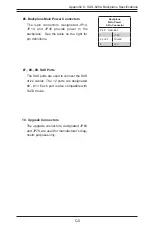
7. Backplane Main Power Connectors
The 4-pin connectors, designated JP10, JP13,
JP46, JP48, JP109, and JP110, provide power
to the backplane. See the table on the right for
pin definitions.
Summary of Contents for SC847 Series
Page 12: ...SC847 Chassis Manual 1 4 Notes...
Page 32: ...2 20 SC847 Chassis Manual Notes...
Page 53: ...5 15 Chapter 5 Chassis Setup and Maintenance Figure 5 14 Placing the System Fan...
Page 76: ...SC847 Chassis Manual B 2 Notes...
Page 86: ...C 10 SC847 Chassis Manual Notes...
Page 96: ...D 10 SC847 Chassis Manual Notes...
Page 118: ...E 22 SC847 Chassis Manual Notes...
Page 187: ...H 23 Appendix H SAS2 846EL Backplane Specifications Notes...


