background image

2-6

SC847BE1C/2C Chassis Manual

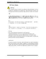
Power Disconnection Warning

 電源切断の警告

システムコンポーネントの取り付けまたは取り外しのために、シャーシー内部にアクセス

するには、

システムの電源はすべてのソースから切断され、電源コードは電源モジュールから取り

外す必要があります。

警告

在你打开机箱并安装或移除内部器件前,必须将系统完全断电,并移除电源线。

警告

在您打開機殼安裝或移除內部元件前,必須將系統完全斷電,並移除電源線。

Warnung 

Das System muss von allen Quellen der Energie und vom Netzanschlusskabel 

getrennt sein, das von den Spg.Versorgungsteilmodulen entfernt wird, bevor es 

auf den Chassisinnenraum zurückgreift, um Systemsbestandteile anzubringen oder 

zu entfernen.

 Warning!

The system must be disconnected from all sources of power and the power cord 

removed from the power supply module(s) before accessing the chassis interior to 

install or remove system components. 

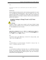
경고!

이 제품은 전원의 단락(과전류)방지에 대해서 전적으로 건물의 관련 설비에 
의존합니다. 보호장치의 정격이 반드시 60V(볼트), 20A(암페어)를 초과하지 
않도록 해야 합니다.

Waarschuwing 

Dit product is afhankelijk van de kortsluitbeveiliging (overspanning) van 

uw electrische installatie. Controleer of het beveiligde aparaat niet groter 

gedimensioneerd is dan 60V, 20A.

Summary of Contents for SC847BE1C series

Page 1: ...SC847BE1C 2C CHASSIS SERIES USER S MANUAL 1 0a SUPER SC847BE1C R1K28LPB SC847BE2C R1K28LPB SC847BE1C R1K28WB SC847BE2C R1K28WB...

Page 2: ...Y HARDWARE SOFTWARE OR DATA STORED OR USED WITH THE PRODUCT INCLUDING THE COSTS OF REPAIRING REPLACING INTEGRATING INSTALLING OR RECOVERING SUCH HARDWARE SOFTWARE OR DATA Any disputes arising between...

Page 3: ...Super Micro Computer B V Het Sterrenbeeld 28 5215 ML s Hertogenbosch The Netherlands Tel 31 0 73 6400390 Fax 31 0 73 6416525 Email sales supermicro nl General Information support supermicro nl Techni...

Page 4: ...icians It provides information for the installation and use of the SC847BEC1 C2 chassis Installation and maintenance should be performed by experienced technicians only This manual lists compatible pa...

Page 5: ...ls on the system interface which includes the func tions and information provided by the chassis control panel as well as other LEDs located throughout the system Chapter 4 Chassis Setup and Maintenan...

Page 6: ...r to the Supermicro website at www supermicro com Appendix C BPN SAS3 846EL Backplane Speciications This chapter contains information on the BPN SAS3 846EL1 and BPN SAS3 846EL2 backplanes Additional i...

Page 7: ...9 Battery Handling 2 10 Redundant Power Supplies 2 12 Backplane Voltage 2 13 Comply with Local and National Electrical Codes 2 14 Product Disposal 2 15 Hot Swap Fan Warning 2 16 DC Power Supply 2 18...

Page 8: ...recautions 5 2 Rack Mounting Considerations 5 3 Ambient Operating Temperature 5 3 Reduced Airlow 5 3 Mechanical Loading 5 3 Circuit Overloading 5 3 Reliable Ground 5 3 5 5 Rack Mounting Instructions 5...

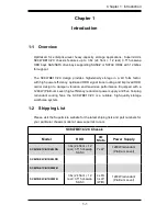
Page 9: ...performance Equipped with a 1280W Platinum Level high eficiency redundant power supply and ive hot plug redundant cooling fans the SC847BE1C 2C is a reliable high quality storage workhorse system 1 2...

Page 10: ...em To en sure the highest level of professional service and technical support we strongly recommend purchasing exclusively from our Supermicro Authorized Distributors System Integrators Resellers A li...

Page 11: ...must be mailed when service is complete For faster service RMA authorizations may be requested online http www supermicro com support rma Whenever possible repack the chassis in the original Supermicr...

Page 12: ...SC847BE1C 2C Chassis Manual 1 4 Notes...

Page 13: ...artment for assistance Only certiied technicians should attempt to install or conigure components Read this appendix in its entirety before installing or coniguring components in the Supermicro chassi...

Page 14: ...idere los riesgos de la corriente el ctrica y familiar cese con los procedimientos est ndar de prevenci n de accidentes Al inal de cada advertencia encontrar el n mero que le ayudar a encontrar el tex...

Page 15: ...l kan veroorzaken Voordat u aan enige apparatuur gaat werken dient u zich bewust te zijn van de bij een elektrische installatie betrokken risico s en dient u op de hoogte te zijn van de standaard proc...

Page 16: ...des Systems an die Stromquelle die Installationsanweisungen lesen Advertencia Lea las instrucciones de instalaci n antes de conectar el sistema a la red de alimentaci n Attention Avant de brancher le...

Page 17: ...liert ist Stellen Sie sicher dass der Nennwert der Schutzvorrichtung nicht mehr als 60VDC 20A betr gt Advertencia Este equipo utiliza el sistema de protecci n contra cortocircuitos o sobrecorrientes d...

Page 18: ...um Systemsbestandteile anzubringen oder zu entfernen Warning The system must be disconnected from all sources of power and the power cord removed from the power supply module s before accessing the c...

Page 19: ...ponentes de sistema Attention Le syst me doit tre d branch de toutes les sources de puissance ainsi que de son cordon d alimentation secteur avant d acc der l int rieur du chassis pour installer ou en...

Page 20: ...g Das Installieren Ersetzen oder Bedienen dieser Ausr stung sollte nur geschultem qualiiziertem Personal gestattet werden Advertencia Solamente el personal caliicado debe instalar reemplazar o utiliza...

Page 21: ...nstallation in Bereichen mit beschr nktem Zutritt vorgesehen Der Zutritt zu derartigen Bereichen ist nur mit einem Spezialwerkzeug Schloss und Schl ssel oder einer sonstigen Sicherheitsvorkehrung m gl...

Page 22: ...r equivalent type recommended by the manufacturer Dispose of used batteries according to the manufacturer s instructions Waarschuwing Dit apparaat is bedoeld voor installatie in gebieden met een beper...

Page 23: ...recommand e par le fabricant Jeter les piles usag es conform ment aux instructions du fabricant Advertencia Existe peligro de explosi n si la bater a se reemplaza de manera incorrecta Reemplazar la b...

Page 24: ...fuentes de alimentaci n Para cortar por completo el suministro de energ a deben desconectarse todas las conexiones Attention Cette unit peut avoir plus d une connexion d alimentation Pour supprimer t...

Page 25: ...asero es peligroso Tenga cuidado cuando lo revise Attention Lorsque le syst me est en fonctionnement des tensions lectriques circulent sur le fond de panier Prendre des pr cautions lors de la maintena...

Page 26: ...ical codes Warnung Die Installation der Ger te muss den Sicherheitsstandards entsprechen Advertencia La instalacion del equipo debe cumplir con las normas de electricidad locales y nacionales Backplan...

Page 27: ...tional laws and regulations Attention L quipement doit tre install conform ment aux normes lectriques nationales et locales Waarschuwing Bij installatie van de apparatuur moet worden voldaan aan de lo...

Page 28: ...ir todas las leyes y reglamentos nacionales Attention La mise au rebut ou le recyclage de ce produit sont g n ralement soumis des lois et ou directives de respect de l environnement Renseignez vous au...

Page 29: ...os dedos los destornilladores y todos los objetos lejos de las aberturas del ventilador Attention Il est possible que les ventilateurs soient toujours en rotation lorsque vous retirerez le bloc ventil...

Page 30: ...schl sse z B f r einen geschlossenen Regelkreis oder gabelf rmig mit nach oben gerichteten Kabelschuhen zu verwenden Diese Abschl sse sollten die angemessene Gr e f r die Dr hte haben und sowohl die I...

Page 31: ...de la taille qui convient aux ils et doivent tre referm es sur la gaine isolante et sur le conducteur Waarschuwing Wanneer geslagen bedrading vereist is dient u bedrading te gebruiken die voorzien is...

Page 32: ...f hrung der folgenden Vorg nge ist sicherzustellen da die Gleichstromschaltung keinen Strom erh lt Advertencia Antes de proceder con los siguientes pasos comprobar que la alimentaci n del circuito de...

Page 33: ...latie als de geleider vast te klemmen Hazardous voltage or energy may be present on DC power terminals Always replace cover when terminals are not in service Be sure uninsulated conductors are not acc...

Page 34: ...ectrique des terminaux courant continu peuvent tre dangereux Veillez toujours replacer le couvercle lors les terminaux ne sont pas en service Assurez vous que les conducteurs non isol s ne sont pas ac...

Page 35: ...you constantly informed of the overall status of the system as well as the activity and health of speciic components SC847EC1 C2 JBOD models have two buttons on the chassis control panel A reset butt...

Page 36: ...server system Turning off system power with this button removes the main power but keeps standby power supplied to the system Therefore you must unplug system before servicing 3 2 Control Panel Butto...

Page 37: ...failure When con tinuously on not lashing it indicates an overheat condition which may be caused by cables obstructing the airlow in the system or the ambient room temperature being too warm Check th...

Page 38: ...LED When illuminated in a solid on state this blue LED on the front of the SAS SATA drive carrier indicates drive activity A connection to the SAS SATA backplane enables this LED to blink on and off...

Page 39: ...erence while setting up your chassis Review the warnings and precautions listed in the manual before setting up or servicing this chassis These include information in Chapter 2 System Safety and the w...

Page 40: ...do NOT operate the server without the cover in place The chassis cover must be in place to allow proper airlow and prevent overheating Removing the Chassis Cover 1 Power down the system and remove the...

Page 41: ...47BE1C 2C chassis has hot swappable 3 5 hard drives which may be removed from the chassis without powering down the system Removing Hard Drive Carriers from the Chassis 1 Press the release button on t...

Page 42: ...and remove the dummy drive Place the hard drive carrier on a lat surface such as a desk table or work bench Warning Except for short periods of time while swapping hard drives do not operate the serv...

Page 43: ...es in both the drive carrier and the hard drive 4 Secure the hard drive to the carrier using six screws 5 Replace the drive tray into the chassis Make sure to close the drive carrier handle to lock th...

Page 44: ...emove part A 1 from the air shroud Installing the 2 5 Hard Drive Cage Into the Chassis 1 Power down the system and remove the power cords from the rear of the power supplies Remove the chassis cover a...

Page 45: ...o Carriers 1 Remove the four screws securing the dummy drive from the drive carrier and set them aside for later use 2 Lift the dummy drive out of the carrier 3 Place a hard drive into the carrier wit...

Page 46: ...e an optional standoff you must place the hexagonal screw through the bottom the chassis and secure the screw with the hexagon nut rounded side up Installing the Motherboard 1 Review your motherboard...

Page 47: ...rd to the tray using the rounded Phillips head screws Do not exceed eight inch pounds of torque 6 Secure the CPUs heatsinks and other components to the motherboard as described in the motherboard docu...

Page 48: ...2 lay the chassis on a lat surface and open the chassis cover 2 Remove the screw holding the PCI slot cover in place in each low proile PCI slot you want to use Keep this screw for later use PCI Slots...

Page 49: ...power cords from the rear of the power supplies Remove the chassis cover as described in Section 4 2 2 Remove the two side screws securing the front backplane to the chassis 3 Remove the four horizon...

Page 50: ...s as illustrated Figure 4 14 Removing the Three Screws Securing the Backplane Figure 4 13 Removing the Two Horizontal Screws Securing the Backplane 4 Remove the four horizontal screws going through th...

Page 51: ...R1K28LPB SC847BE1C 2C R1K28WB 1 3 1 3 1 4 1 4 Figure 4 15 Installing the Front Backplane SC847BE1C 2C R1K28LPB SC847BE1C 2C R1K28WB 1 2 1 2 3 Install the two side screws to secure the front backplane...

Page 52: ...8WB Figure 4 17 Installing the Rear Backplane SC847BE1C 2C R1K28LPB SC847BE1C 2C R1K28WB 1 3 1 3 1 2 1 2 3 Place the rear backplane in the chassis and secure it with the three vertical screws along th...

Page 53: ...825 826 216 213 universal air shroud com ponent Carefully pull this component from the main body of the air shroud in the direction shown by the arrows above C MCP 310 49007 1N X9 SC847 417 universal...

Page 54: ...gned with removeable break away tabs that allow the air shroud to be adjusted to it a variety of motherboards Installing the Air Shroud 1 Power down the system as described in Section 5 2 and remove t...

Page 55: ...Make sure no wires or foreign objects obstruct air low through the chassis Pull all excess cabling out of the airlow path or use shorter cables The control panel LEDs inform you of the system s statu...

Page 56: ...tended period of time with the chassis cover open 2 Remove the failed fan s power cord from the serverboard 3 Press the fan release tab to lift the failed fan from the chassis and pull it completely o...

Page 57: ...4 19 Chapter 4 Chassis Setup and Maintenance Figure 4 22 Placing the System Fan...

Page 58: ...power supplies are hot swappable and can be changed without pow ering down the system New units can be ordered directly from Supermicro see contact information in the Preface Changing the Power Supply...

Page 59: ...wer Supply Release Tab 1 4 4 Replace the failed power module with the same model 5 Push the new power supply module into the power bay until you hear a click 6 If using only one power supply plug the...

Page 60: ...SC847BE1C 2C Chassis Manual 4 22 Notes...

Page 61: ...nerated The system needs to be placed near a grounded power outlet Be sure to read the Rack and Server Precautions in the next section 5 3 Preparing for Setup The box your chassis was shipped in shoul...

Page 62: ...se the rack to become unstable General Server Precautions Review the electrical and general safety precautions that came with the com ponents you are adding to your chassis Determine the placement of...

Page 63: ...ossible overloading of circuits might have on overcurrent protection and power supply wiring Appropriate consideration of equipment nameplate ratings should be used when addressing this concern Reliab...

Page 64: ...rack between 26 5 and 36 4 deep Identifying the Sections of the Rack Rails The chassis package includes two rail assemblies in the rack mounting kit Each assembly consists of three sections An inner...

Page 65: ...the rack This prevents the server from coming completely out of the rack when when the chassis is pulled out for servicing Releasing the Inner Rail Releasing Inner Rail from the Outer Rails 1 Identify...

Page 66: ...de of the chassis aligning the hooks on the side of the chassis with the holes in the inner rail 3 Slide the inner rail forward toward the front of the chassis until the rail clicks into the locked po...

Page 67: ...of the rack If necessary use screws to secure the outer rails to the rack as illustrated above 4 Pull out the rear of the outer rail adjusting the length until it its within the posts of the rack 5 H...

Page 68: ...the front of the middle rail locking the chassis into the fully extended position 6 Depress the locking tabs of both sides at the same time and push the chassis all the way into the rear of the rack...

Page 69: ...is onto a rack Installing the Chassis into a Rack 1 Install the whole rail assembly onto the rack as described on page X 7 2 Release the inner rail without retracting the middle rail 3 Install the inn...

Page 70: ...SC847BE1C 2C Chassis Manual 5 10 Notes...

Page 71: ...refer to the manufacturer of the motherboard you are using and our Web site at www supermicro com A 2 Cables Included with SC847BE1C 2C Chassis SC847BE1C 2C R1K28LPB SC847BE1C 2C R1K28WB Part Type Qt...

Page 72: ...1 Part CBL 0175L Alt Name Big Four Alternate SAS SATA Cables Some compatible motherboards have different connectors If your motherboard has only one SAS connector that the SAS SATA cables must share...

Page 73: ...CBL 0059 7 9 20 cm 8 pin CBL 0062 7 9 20 cm 4 pin CBL 0060 7 9 20 cm Front Panel to the Motherboard The SC847BE1C 2C chassis includes a cable to connect the chassis front panel to the motherboard If...

Page 74: ...head M4 x 4 mm 0 157 RAIL Round head M4 x 4 mm 0 157 Flat head M5 x 12 mm 0 472 Washer for M5 DVD ROM CD ROM and FLOPPY DRIVE Flat head 6 32 x 5 mm 0 197 Pan head 6 32 x 5 mm 0 197 Round head M3 x 5 m...

Page 75: ...ations This appendix lists power supply speciications for your chassis system SC847BE1C 2C R1K28LPB SC847BE1C 2C R1K28WB 1280W MFR Part PWS 1K28P SQ AC Input 1000W Output 100 140V 12 8A 50 60Hz 1280W...

Page 76: ...SC847BE1C 2C Chassis Manual B 2 Notes...

Page 77: ...rom ESD Use a grounded wrist strap designed to prevent static discharge Touch a grounded metal object before removing a component from the antistatic bag Handle the backplane by its edges only do not...

Page 78: ...l relects BPN SAS3 846EL Revision 1 01 the most current release available at the time of publication Always refer to the Supermicro website at www supermicro com for the latest updates compatible part...

Page 79: ...0 MH19 MH18 MH17 MH16 ACTLED HS2 HS1 J30 JP3 J31 JP4 J24 J29 U51 Q873 Q866 Q872 Q871 Q868 Q867 Q870 Q869 U25 U20 U29 U26 U27 U28 U31 U30 U37 U33 U1 EC23 C382 C383 EC9 EC8 EC7 EC6 EC5 EC4 EC3 EC2 EC12...

Page 80: ...designated J49 and J50 The secondary SAS Ports are designated J51 through J52 and are not pres ent on EL1 single port backplanes 6 7 Primary and Secondary UART Con nectors The primary UART connector i...

Page 81: ...51 Q873 Q866 Q872 Q871 Q868 Q867 Q870 Q869 U25 U20 U29 U26 U27 U28 U31 U30 U37 U33 U1 EC23 C382 C383 EC9 EC8 EC7 EC6 EC5 EC4 EC3 EC2 EC12 EC11 EC10 EC1 EC24 EC22 EC21 EC20 EC19 EC18 EC17 EC16 EC15 EC1...

Page 82: ...E7 G7 H7 H8 E8 PRESS FIT CG5 CG2 BPN SAS3 846EL2 REV 1 01 DESIGNED IN USA 1 1 4 1 4 1 4 1 4 1 4 1 4 14 6 7 8 13 2 6 7 8 9 13 11 12 22 11 12 22 11 11 12 22 11 12 22 11 12 22 12 13 14 23 2 11 12 13 14 2...

Page 83: ...17 ACT16 B ACT 3 FAIL 3 ACT 2 FAIL 2 ACT 7 FAIL 7 ACT 6 FAIL 6 1 SAS 0 SAS 6 SAS 7 SAS 13 SAS SAS 12 ACT 12 FAIL 12 FAIL 13 ACT 13 ACT 18 FAIL 18 ACT 19 FAIL 19 SAS 18 SAS 19 ACT 23 FAIL 23 ACT 22 FAI...

Page 84: ...FAIL4 SAS 5 ACT5 FAIL5 SAS 6 ACT6 FAIL6 SAS 7 ACT7 FAIL7 SAS 8 ACT8 FAIL8 SAS 9 ACT 9 FAIL9 SAS 10 ACT10 FAIL10 SAS 11 ACT11 FAIL11 SAS 12 ACT12 FAIL12 SAS 13 ACT13 FAIL13 SAS 14 ACT14 FAIL14 SAS 15...

Page 85: ...D8 CG4 E1 E2 G2 F2 F1 H2 H1 G1 F7 F8 G8 E7 G7 H7 H8 E8 PRESS FIT CG5 CG2 A1 A2 A7 A8 CG1 B1 B2 B7 B8 C1 C2 C7 C8 D1 D2 D7 D8 CG4 E1 E2 G2 F2 F1 H2 H1 G1 F7 F8 G8 E7 G7 H7 H8 E8 PRESS FIT CG5 CG2 BPN...

Page 86: ...le host bus coniguration the backplane connects to one host bus adapter Single Host Bus Adapter Failover If the expander or data path in Port A fails the system automatically switches to Port B with a...

Page 87: ...CG5 CG2 A1 A2 A7 A8 CG1 B1 B2 B7 B8 C1 C2 C7 C8 D1 D2 D7 D8 CG4 E1 E2 G2 F2 F1 H2 H1 G1 F7 F8 G8 E7 G7 H7 H8 E8 PRESS FIT CG5 CG2 BPN SAS3 846EL2 REV 1 01 DESIGNED IN USA 1 1 4 1 4 1 4 1 4 1 4 1 4 14...

Page 88: ...C1 C2 C7 C8 D1 D2 D7 D8 CG4 E1 E2 G2 F2 F1 H2 H1 G1 F7 F8 G8 E7 G7 H7 H8 E8 PRESS FIT CG5 CG2 A1 A2 A7 A8 CG1 B1 B2 B7 B8 C1 C2 C7 C8 D1 D2 D7 D8 CG4 E1 E2 G2 F2 F1 H2 H1 G1 F7 F8 G8 E7 G7 H7 H8 E8 P...

Page 89: ...or 36 pin at one end and a Mini SAS HD SFF 8643 connector at the other end It connects from the SAS2 HBA to the BPN SAS3 846EL model backplane Cable name Internal HD Mini SAS to HD Mini SAS Part CBL S...

Page 90: ...E1 E2 G2 F2 F1 H2 H1 G1 F7 F8 G8 E7 G7 H7 H8 E8 PRESS FIT CG5 CG2 A1 A2 A7 A8 CG1 B1 B2 B7 B8 C1 C2 C7 C8 D1 D2 D7 D8 CG4 E1 E2 G2 F2 F1 H2 H1 G1 F7 F8 G8 E7 G7 H7 H8 E8 PRESS FIT CG5 CG2 A1 A2 A7 A8...

Page 91: ...EC1 EC24 EC22 EC21 EC20 EC19 EC18 EC17 EC16 EC15 EC14 EC13 J48 J47 L8 L10 L4 L2 L5 L6 PWR1 PWR2 PWR3 PWR4 PWR5 PWR6 R65 TP95 TP94 TP15 TP36 C128 C135 C233 C236 C206 C24 CS21 CT199 12V_LED2 5V_LED2 5V_...

Page 92: ...cription Internal cable connects the SAS3 backplane to external ports Cable Name 1 Meter External Mini SAS HD to External Mini SAS HD Cable Part CBL SAST 0573 Ports Single Placement External Cable Des...

Page 93: ...Channel Environment This section describes the cables used when cascading from dual HBAs These con nections use CBL SAST 0531 internal cables and CBL SAST 0573 external cables Figure C 17 Dual HBA Co...

Page 94: ...be reasonably expected to result in signiicant injury or loss of life or catastrophic property damage Accordingly Supermicro disclaims any and all liability and should buyer use or sell such products...

Page 95: ...ESD Use a grounded wrist strap designed to prevent static discharge Touch a grounded metal object before removing a component from the antistatic bag Handle the backplane by its edges only do not tou...

Page 96: ...relects BPN SAS3 826EL Revision 1 00 the most current release available at the time of publication Always refer to the Supermicro Web site at www supermicro com for the latest updates compatible parts...

Page 97: ...22 J23 J22 J18 J19 JPW2 JPW1 JPW3 U34 U17 U14 U21 U16 U20 U6 C52 J16 J17 MH7 MH6 MH9 MH8 MH5 MH1 MH2 MH3 MH4 U30 U24 U7 U27 JP1 R97 C511 C5 J J I2C 4 SEC UART PRI UART 12V 5V HB LED HB LED PRI SDB PRI...

Page 98: ...The secondary SAS Ports are designated SED J1 through SED J4 and are not present on EL1 single port backplanes 6 7 Primary and Secondary UART Con nectors The primary UART connector is designated PRI...

Page 99: ...D28 LED27 LED26 LED25 L3 L23 C496 C502 C501 C500 C499 C498 C497 C495 C494 C492 C491 C689 C681 J21 J20 U22 J23 J22 J18 J19 JPW2 JPW1 JPW3 U34 U17 U14 U21 U16 U20 U6 C52 J16 J17 MH7 MH6 MH9 MH8 MH5 MH1...

Page 100: ...4 1 4 1 4 11 12 22 A 1 E 5 H 5 1 A E H A 1 E 5 H 5 1 A E H A1 A2 A7 A8 CG1 CG2 B1 B2 B7 B8 C1 C2 C7 C8 D1 D2 D7 D8 CG3 E1 E2 G2 F2 F1 H2 H1 G1 F7 F8 G8 E7 G7 H7 H8 E8 PRESS FIT A1 A2 A7 A8 CG1 CG2 B1...

Page 101: ...J9 R14 R26 R394 R289 R139 R173 C157 C158 C159 C138 C139 C140 C141 C144 C161 C160 C154 C66 C67 C69 C68 C122 C123 C124 C125 C126 C127 C128 C129 C155 C156 C170 C171 C172 C173 C145 R R R R R R R R R R R...

Page 102: ...D 8 SC847BE1C 2C Chassis Manual Notes...

Page 103: ...E 5 H 5 1 A E H A 1 E 5 H 5 1 A E H A1 A2 A7 A8 CG1 CG2 B1 B2 B7 B8 C1 C2 C7 C8 D1 D2 D7 D8 CG3 E1 E2 G2 F2 F1 H2 H1 G1 F7 F8 G8 E7 G7 H7 H8 E8 PRESS FIT A1 A2 A7 A8 CG1 CG2 B1 B2 B7 B8 C1 C2 C7 C8 D1...

Page 104: ...J21 J20 U22 J23 J22 J18 J19 JPW2 JPW1 JPW3 U34 U17 U14 U21 U16 U20 U6 C52 J16 J17 MH7 MH6 MH9 MH8 MH5 MH1 MH2 MH3 MH4 U30 U24 U7 U27 JP1 R97 C511 C5 J J I2C 4 SEC UART PRI UART 12V 5V HB LED HB LED PR...

Page 105: ...G2 F2 F1 H2 H1 G1 F7 F8 G8 E7 G7 H7 H8 E8 PRESS FIT A1 A2 A7 A8 CG1 CG2 B1 B2 B7 B8 C1 C2 C7 C8 D1 D2 D7 D8 CG3 E1 E2 G2 F2 F1 H2 H1 G1 F7 F8 G8 E7 G7 H7 H8 E8 PRESS FIT 1 5 10 15 20 25 26 Y R K E A...

Page 106: ...500 C499 C498 C497 C495 C494 C492 C491 C689 C681 J21 J20 U22 J23 J22 J18 J19 JPW2 JPW1 JPW3 U34 U17 U14 U21 U16 U20 U6 C52 J16 J17 MH7 MH6 MH9 MH8 MH5 MH1 MH2 MH3 MH4 U30 U24 U7 U27 JP1 R97 C511 C5 J...

Page 107: ...or 36 pin at one end and a Mini SAS HD SFF 8643 connector at the other end It connects from the SAS2 HBA to the BPN SAS3 826EL model backplane Cable name Internal HD Mini SAS to HD Mini SAS Part CBL S...

Page 108: ...LED25 L3 L23 C496 C502 C501 C500 C499 C498 C497 C495 C494 C492 C491 C689 C681 J21 J20 U22 J23 J22 J18 J19 JPW2 JPW1 JPW3 U34 U17 U14 U21 U16 U20 U6 C52 J16 J17 MH7 MH6 MH9 MH8 MH5 MH1 MH2 MH3 MH4 U30...

Page 109: ...C681 J21 J20 U22 J23 J22 J18 J19 JPW2 JPW1 JPW3 U34 U17 U14 U21 U16 U20 U6 C52 J16 J17 MH7 MH6 MH9 MH8 MH5 MH1 MH2 MH3 MH4 U30 U24 U7 U27 JP1 R97 C511 C5 J J I2C 4 SEC UART PRI UART 12V 5V HB LED HB...

Page 110: ...cription Internal cable connects the SAS3 backplane to external ports Cable Name 1 Meter External Mini SAS HD to External Mini SAS HD Cable Part CBL SAST 0573 Ports Single Placement External Cable Des...

Page 111: ...C491 C689 C681 J21 J20 U22 J23 J22 J18 J19 JPW2 JPW1 JPW3 U34 U17 U14 U21 U16 U20 U6 C52 J16 J17 MH7 MH6 MH9 MH8 MH5 MH1 MH2 MH3 MH4 U30 U24 U7 U27 JP1 R97 C511 C5 J J I2C 4 SEC UART PRI UART 12V 5V...

Page 112: ...D 18 SC847BE1C 2C Chassis Manual Notes...
Page 113: ...Use a grounded wrist strap designed to prevent static discharge Touch a grounded metal object before removing a component from the antistatic bag Handle the backplane by its edges only do not touch i...

Page 114: ...EL1 The BPN SAS3 846EL2 is divided into a two sections with the primary components on the right side of the board and the secondary components on the left SAS3 backplanes are not compatible with legac...

Page 115: ...MDIO S_SDB S_UART EXP I2C0 EXP I2C4 5V GND 12V 5V GND 12V 5V GND 12V 5V GND 12V J50 J49 J52 J51 SEC PRI CBL SAST 0573 External Cable Power Card Port A Expander 1 Port B Expander 2 Connecting the Front...

Page 116: ...be reasonably expected to result in signiicant injury or loss of life or catastrophic property damage Accordingly Supermicro disclaims any and all liability and should buyer use or sell such products...

Reviews: